Description
The timeless, stream lined and light design of HALO forms a horizontal throw-pattern. The device suits a wire range of air flow rates making it an ideal option for a variety of projects.
The diffuser forms a truly stylish entity while attached into a ceiling and leaves the space finished up to the smallest details. With its unique attachment mechanism, no attachment structures, adjustment mechanism or ducts are visible from behind the front plate.
For high-class air distribution
Due to its functional construction HALO forms a wide-spread, horizontal throw-pattern quietly and does not cause feeling of draught. The throw-pattern can be directed into 1,2,3, or 4 directions.
While using HALO and FLO plenum box together, the advantages of FLO’s highly accurate and sturdy adjustment mechanism can be attained.
Two options for installation
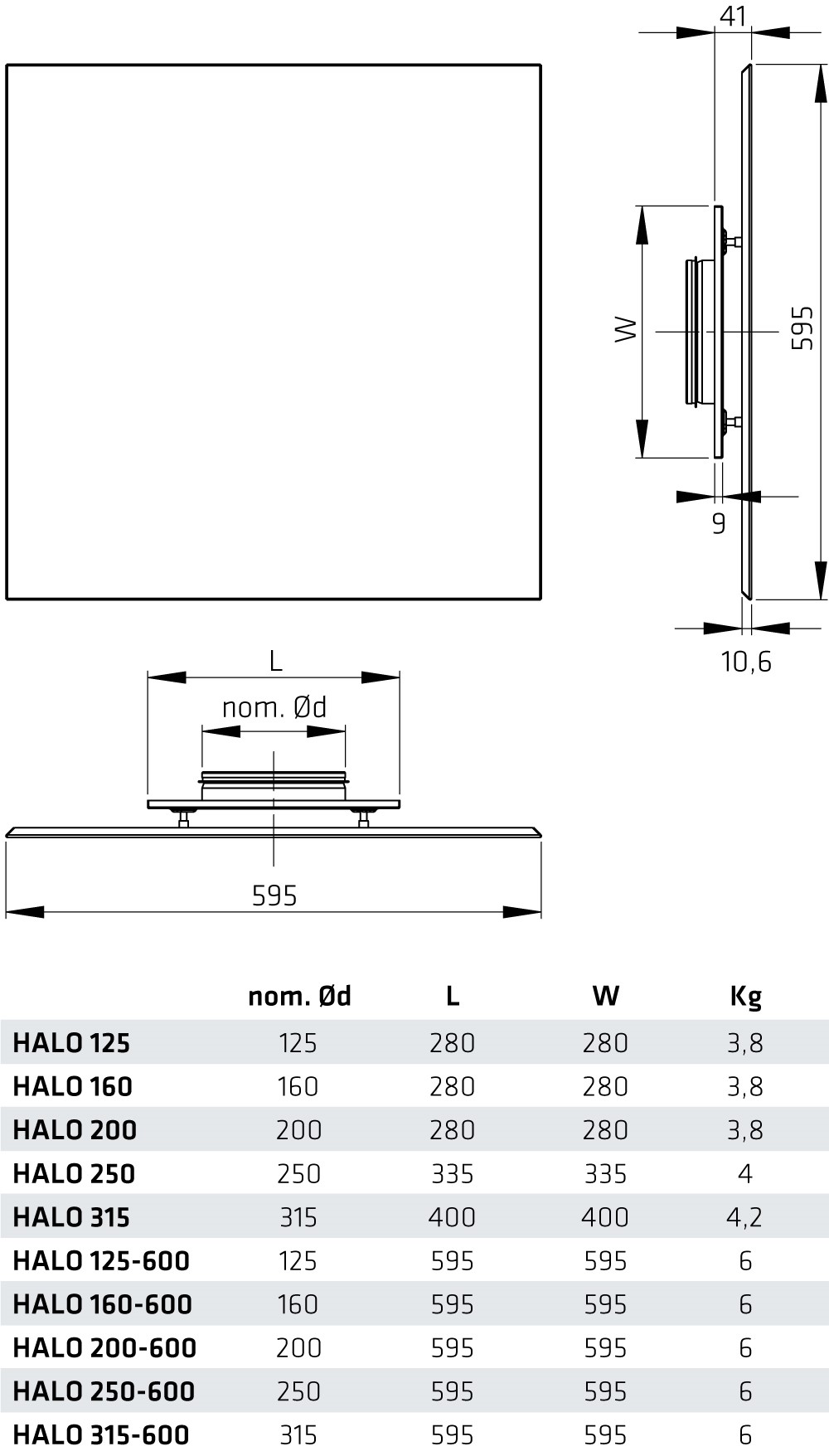
HALO suits coffered ceilings with a 600×600 attachment plate. A smaller collar joint attachment plate can be used when the diffuser is placed on an even ceiling.
HALO diffusers also suit exhaust air. In this case we recommend using FLO plenum box.
Qualities:
- distinctively light and streamlined design
- horizontal throw-pattern
- directable throw-pattern
- two options for attachment plate
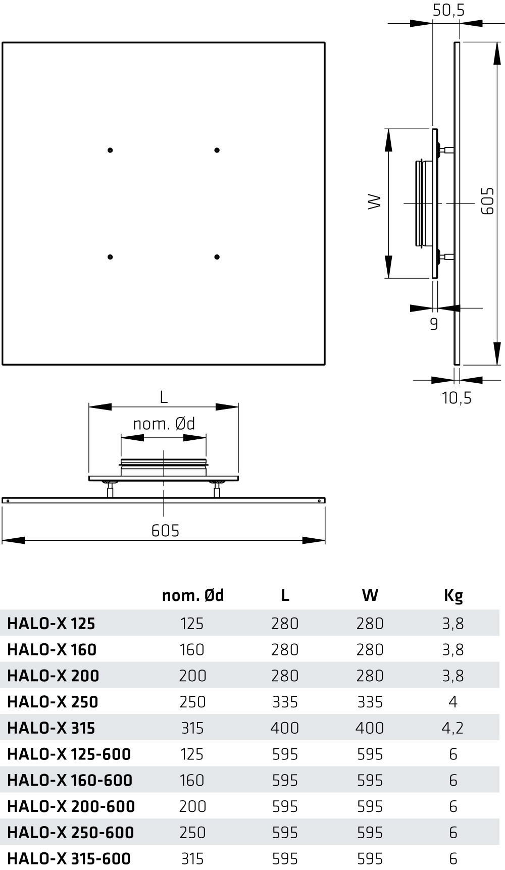
See also design diffuser HALO-X
Product code
| HALO |
– |
X |
– |
125 |
– |
600 |
| 1 |
|
2 |
|
3 |
|
4 |
1 = HALO for supply air, HALOi for exhaust air
2 = HALO-X
3 = Duct size 125-315 mm
4 = with a 600×600 mm attachment plate
HALO-125 = HALO for supply air, for an even ceiling
Dimensioning
Not intended for adjustment.
HALO
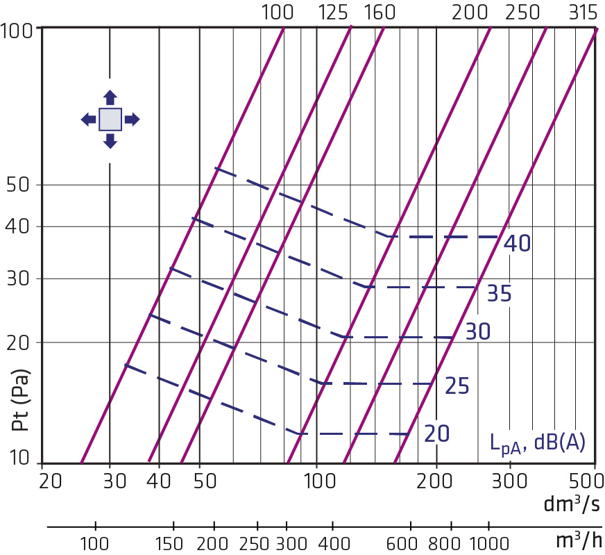
Without plenum box.
Airflow to 4 directions.
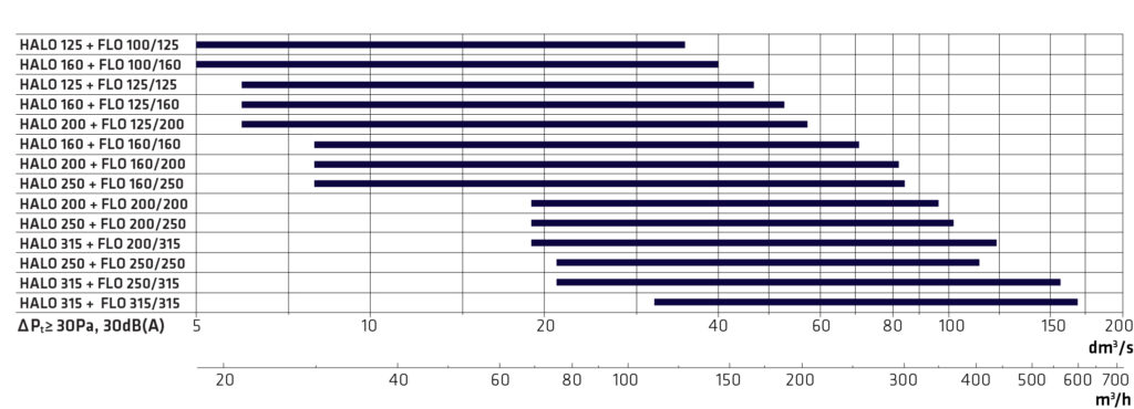
Dimensioning HALO + FLO supply air
Not intended for adjustment.
HALO-125 + FLO-100-125 Supply air
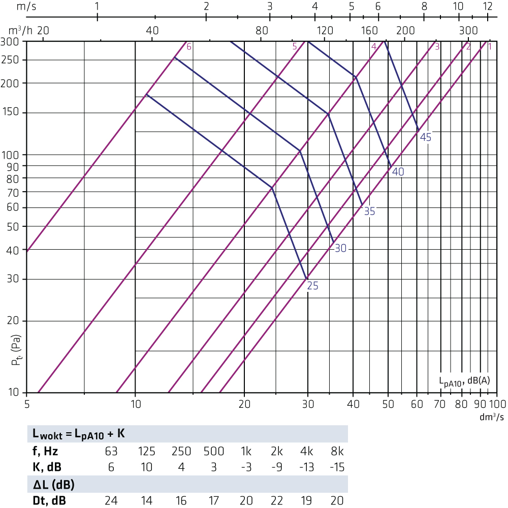
HALO-125 + FLO-125-125 Supply air
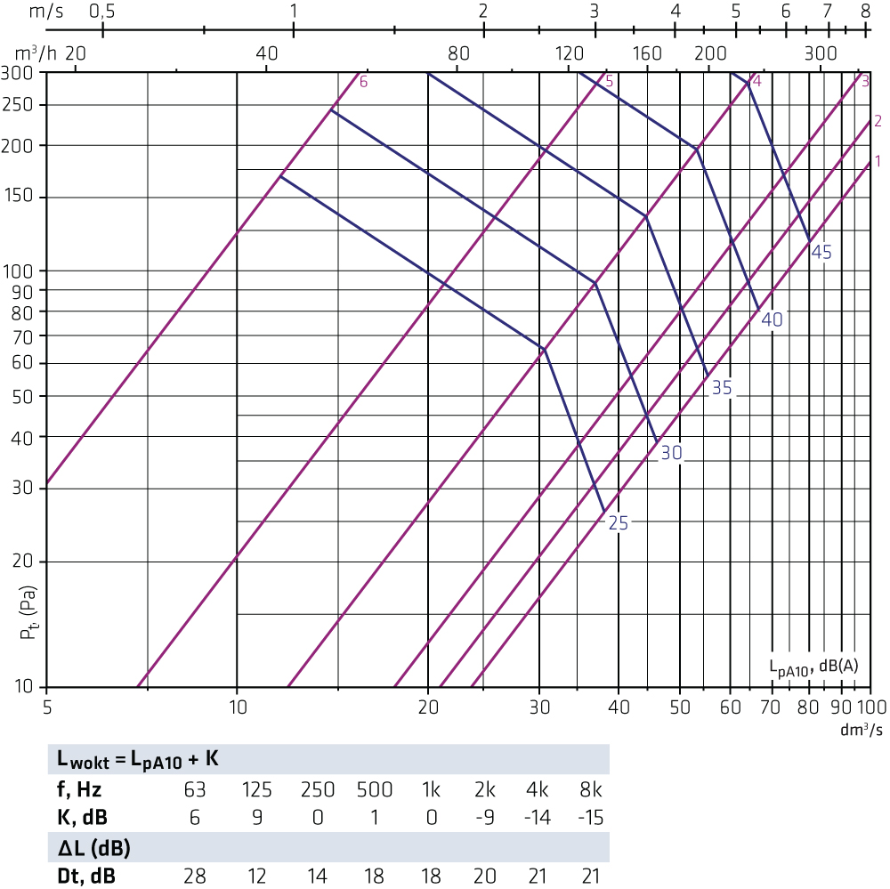
HALO-160 + FLO-100-160 Supply air
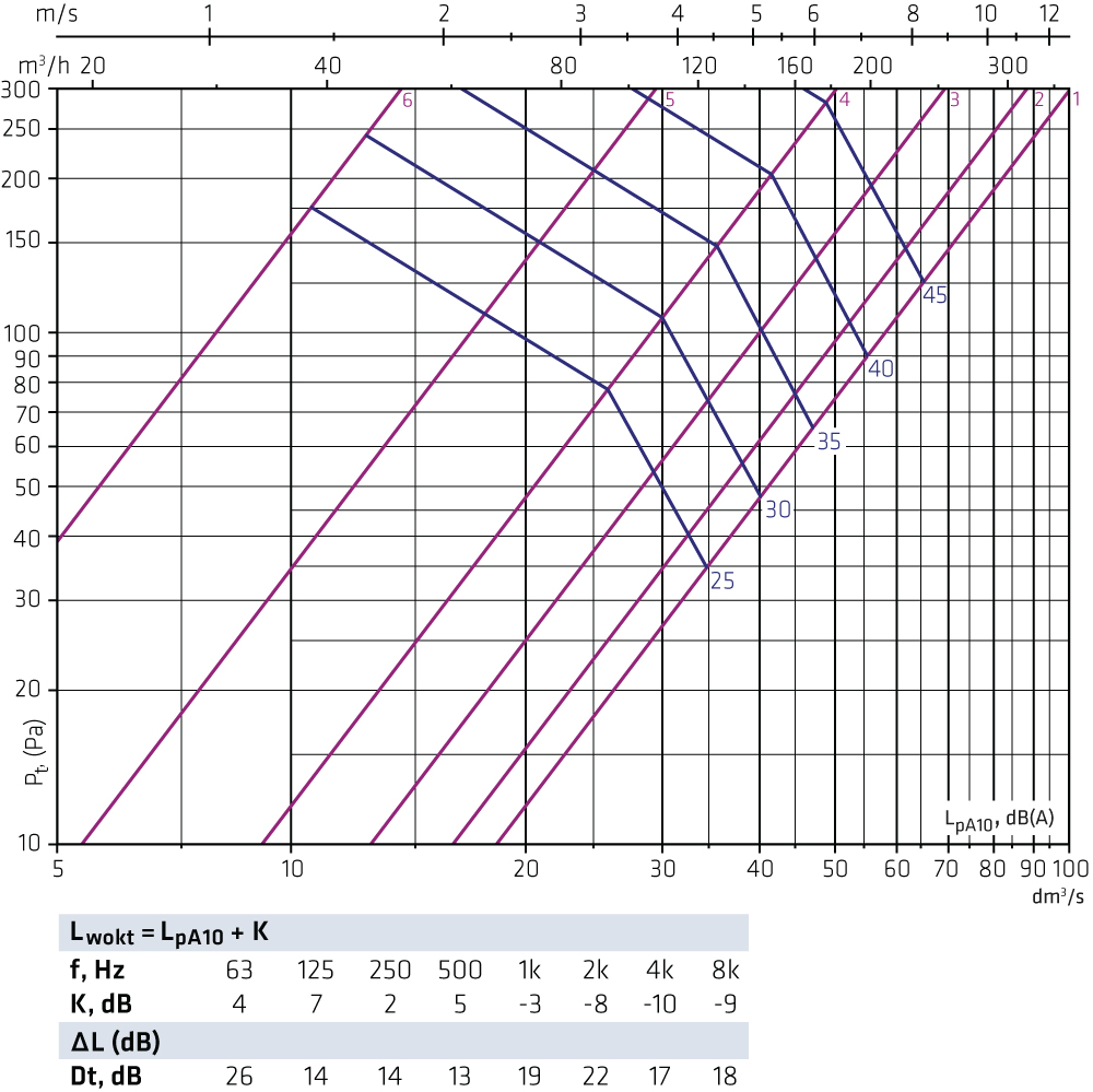
HALO-160 + FLO-125-160 Supply air
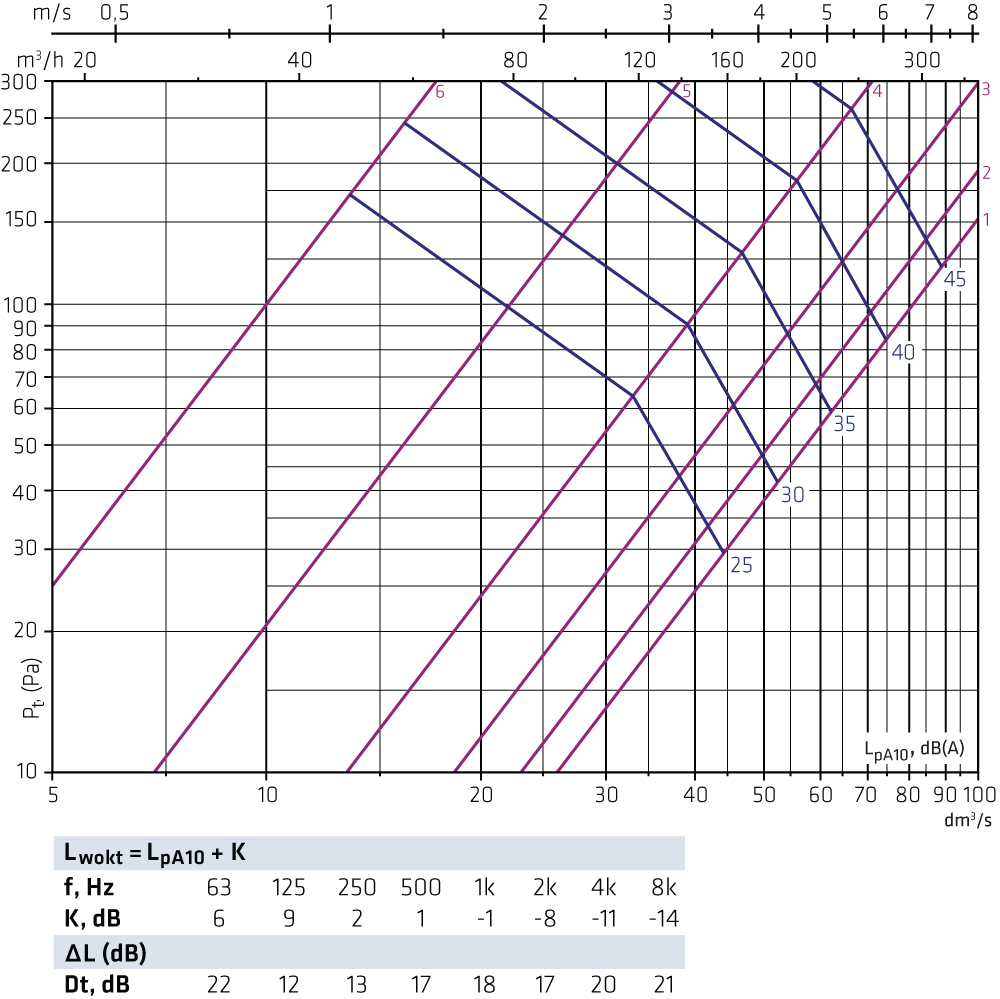
HALO-160 + FLO-160-160 Supply air
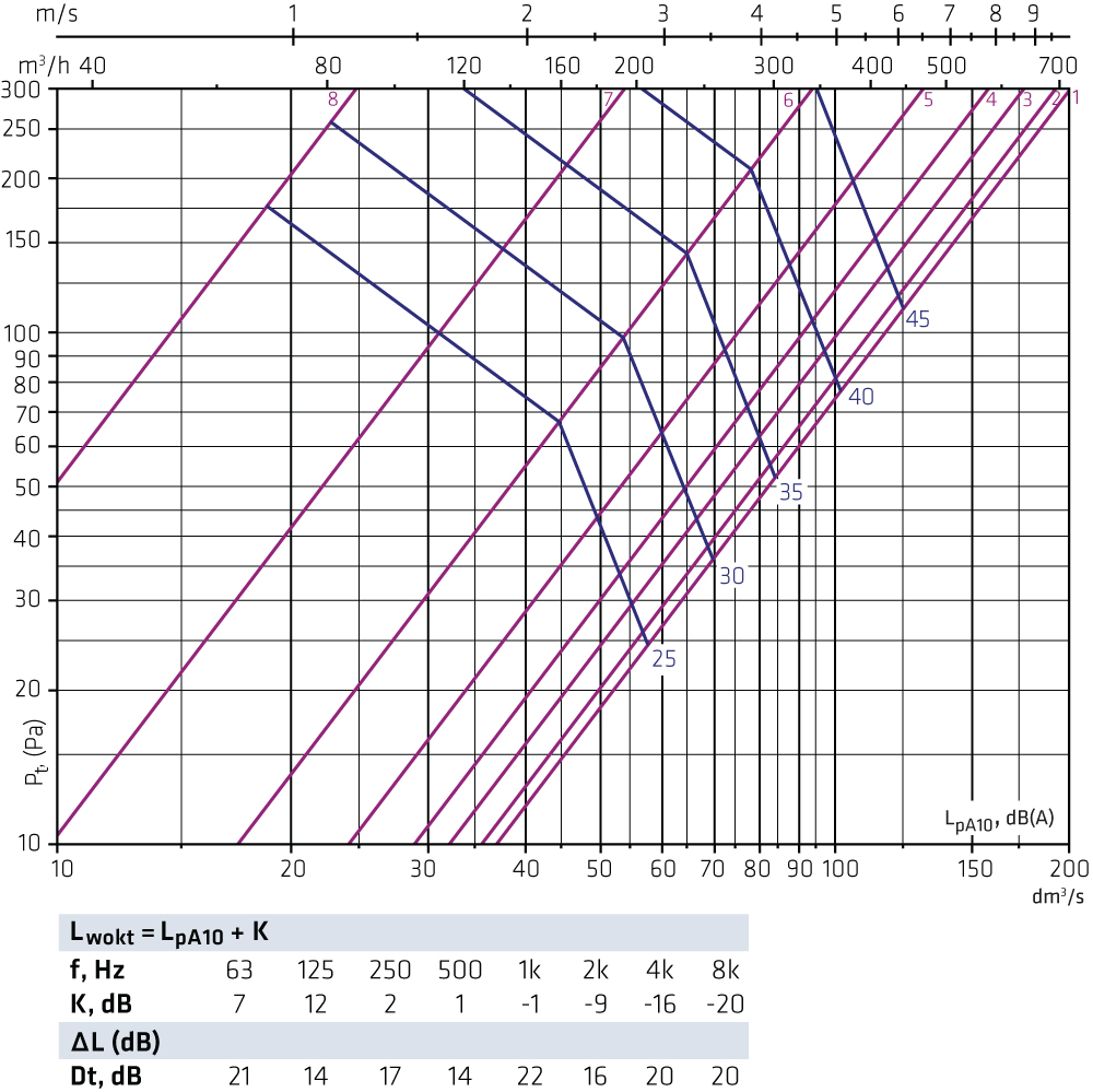
HALO-200 + FLO-125-200 Supply air
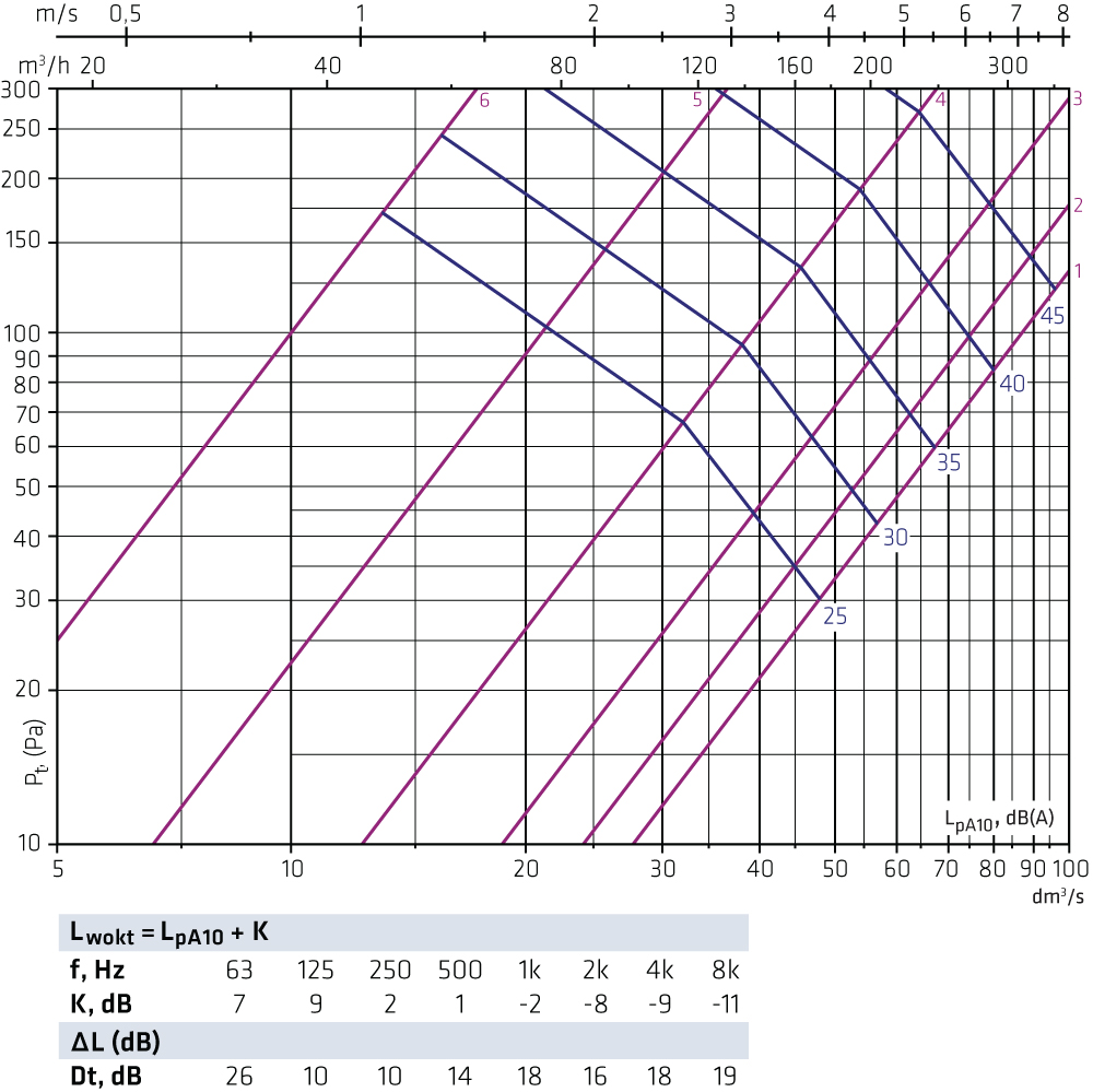
HALO-200 + FLO-160-200 Supply air
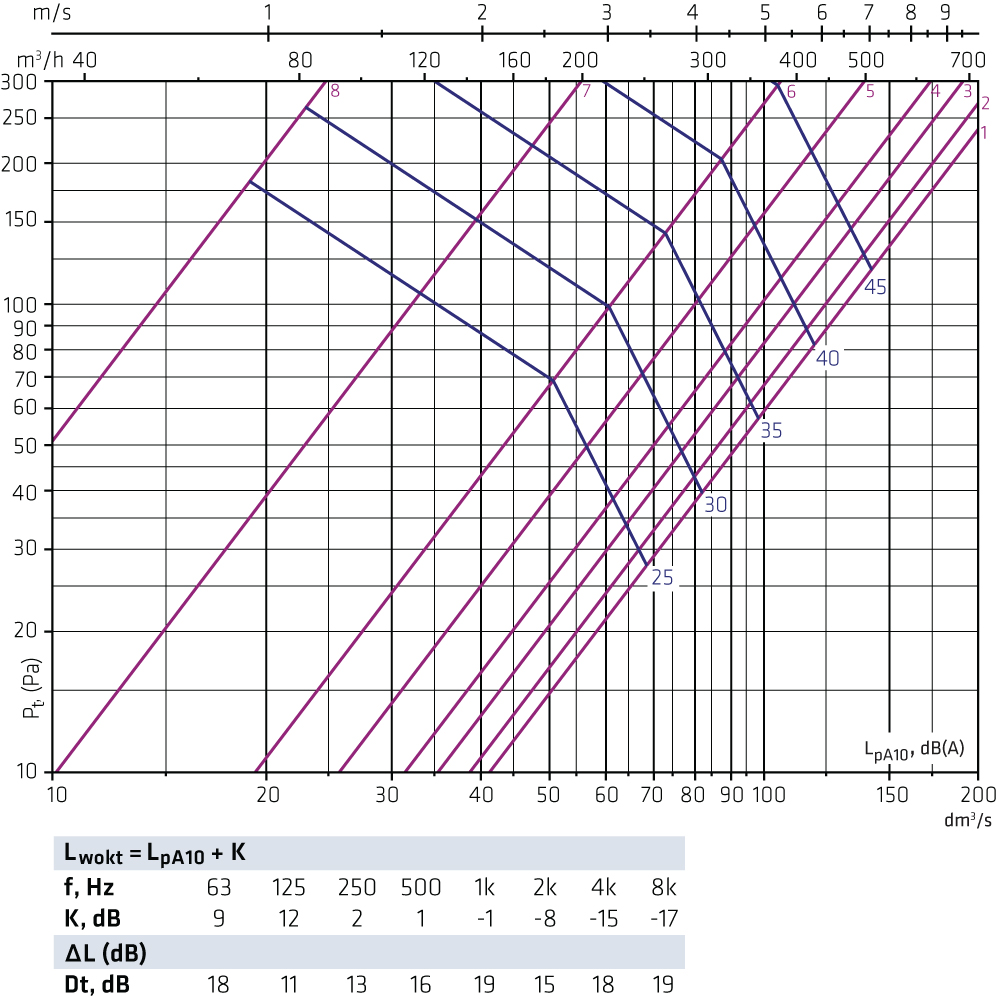
HALO-200 + FLO-200-200 Supply air
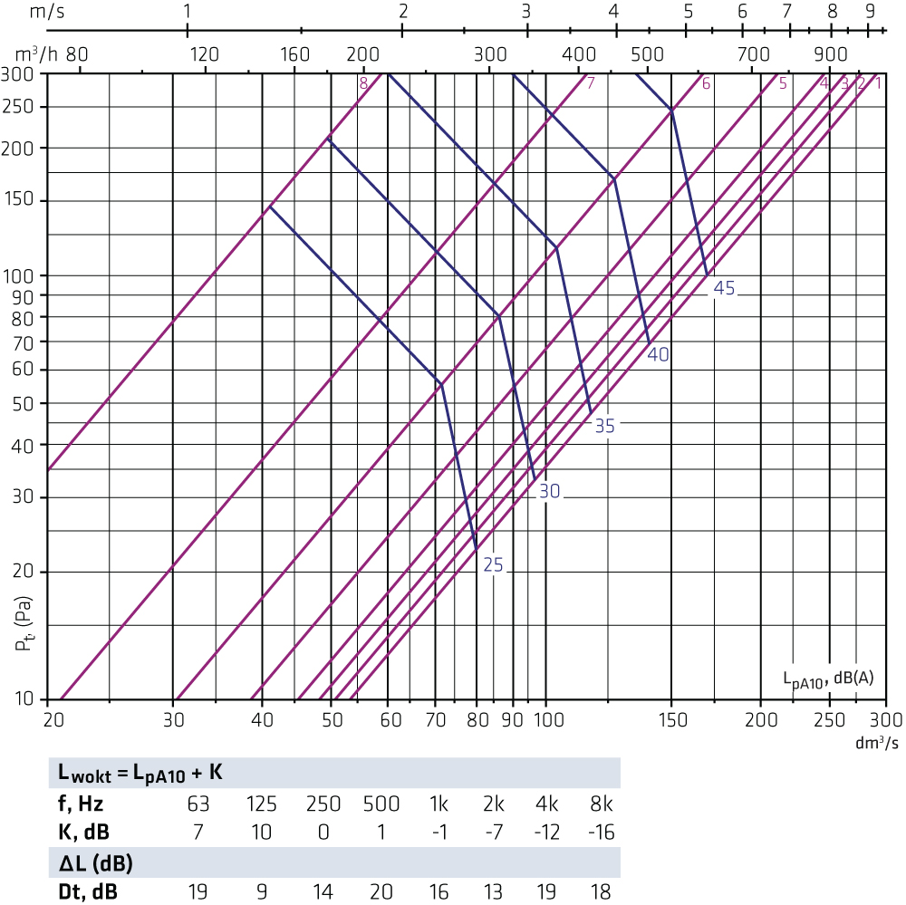
HALO-250 + FLO-160-250 Supply air
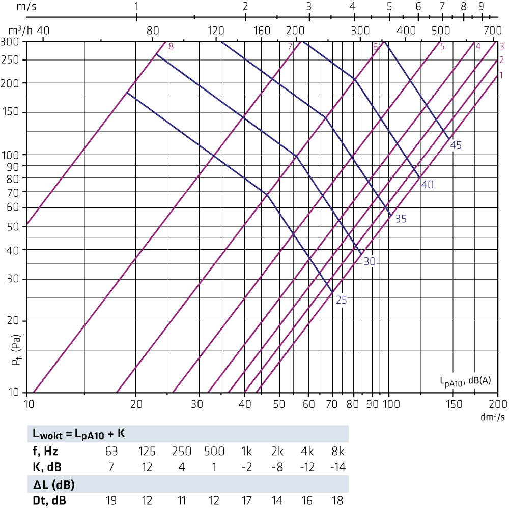
HALO-250 + FLO-200-250 Supply air
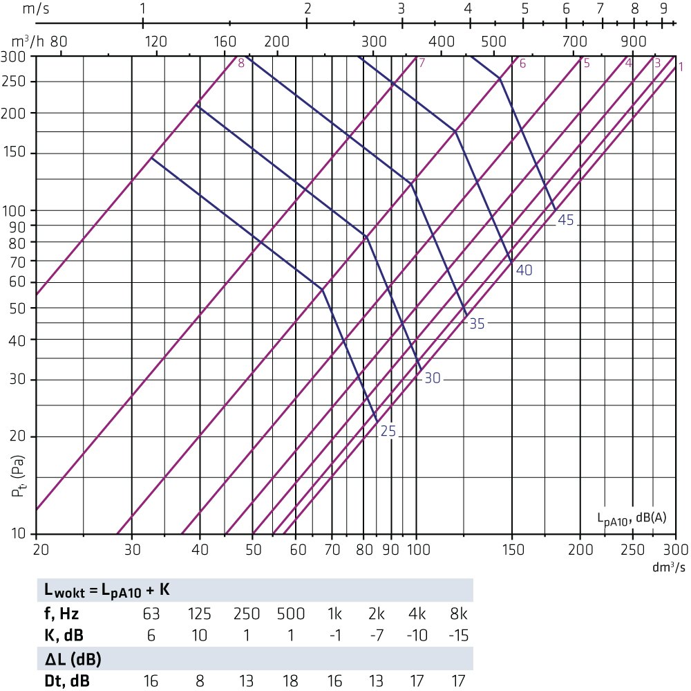
HALO-250 + FLO-250-250 Supply air
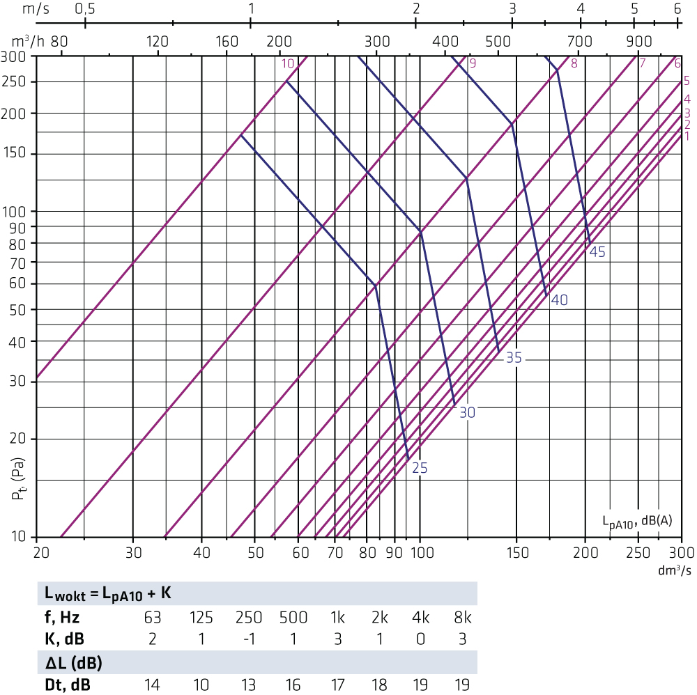
HALO-315 + FLO-200-315 Supply air
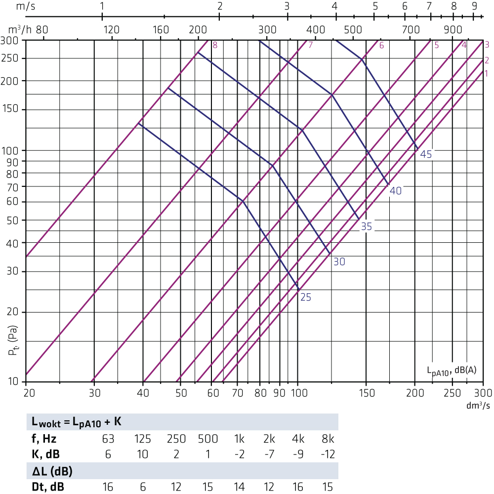
HALO-315 + FLO-250-315 Supply air
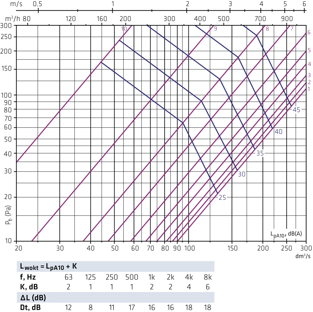
HALO-315 + FLO-315-315 Supply air

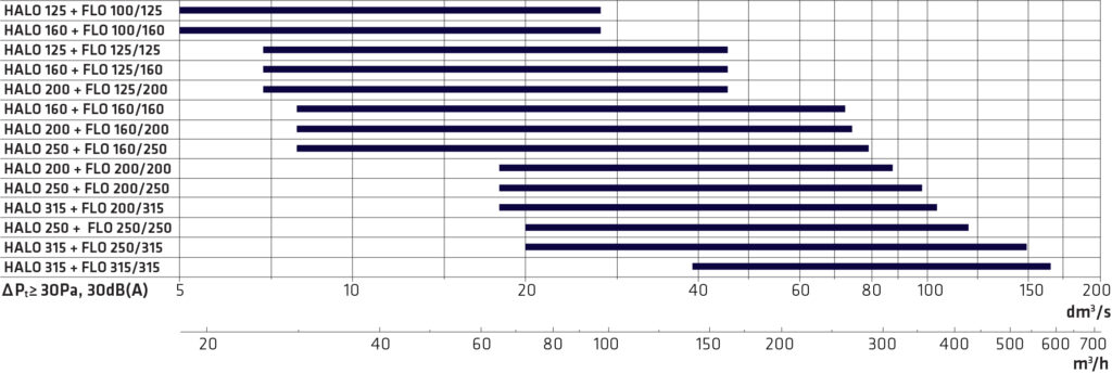
Dimensioning HALO + FLO exhaust air
Not intended for adjustment.
HALOi-125 + FLO-100-125 Exhaust air
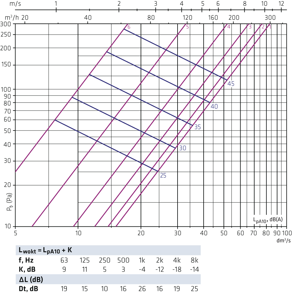
HALOi-125 + FLO-125-125 Exhaust air
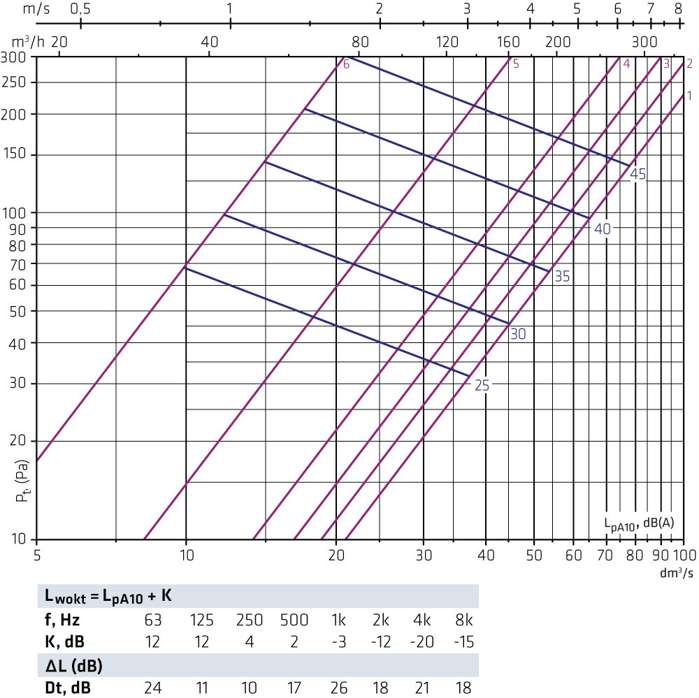
HALOi-160 + FLO-100-160 Exhaust air
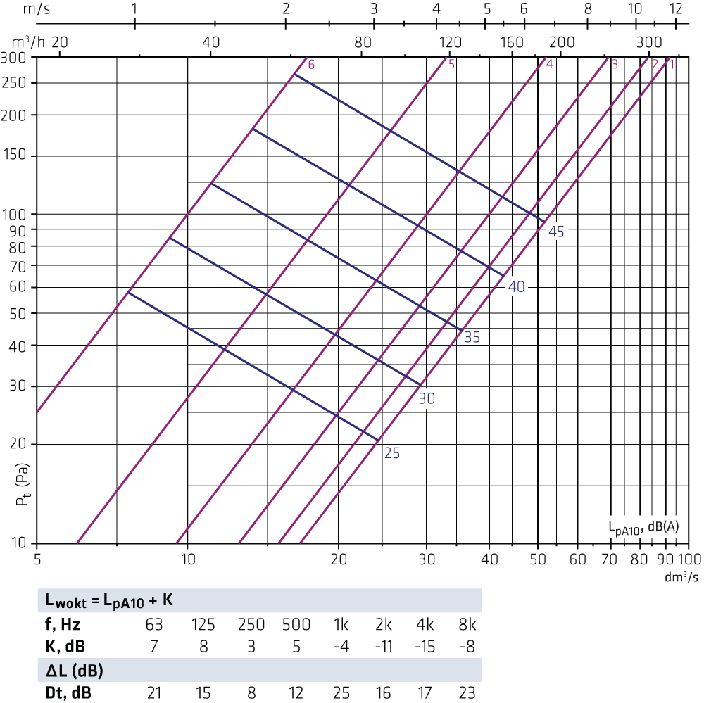
HALOi-160 + FLO-125-160 Exhaust air
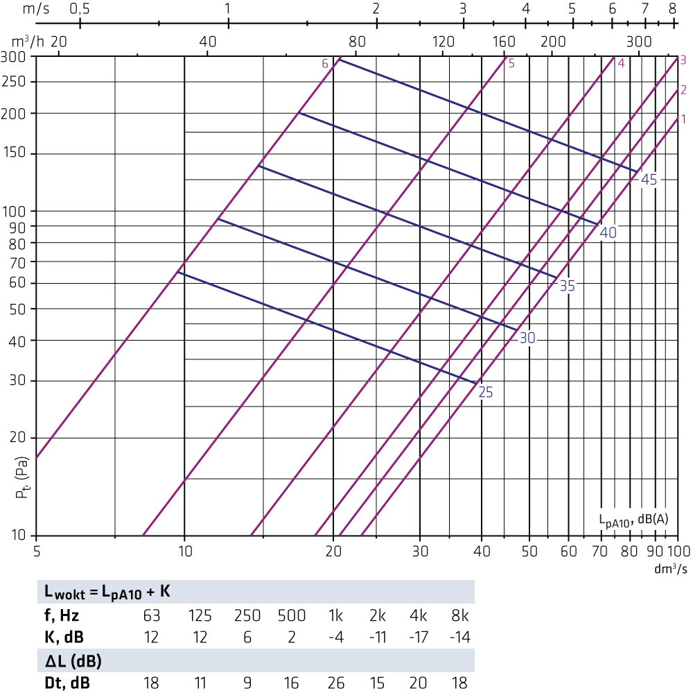
HALOi-160 + FLO-160-160 Exhaust air
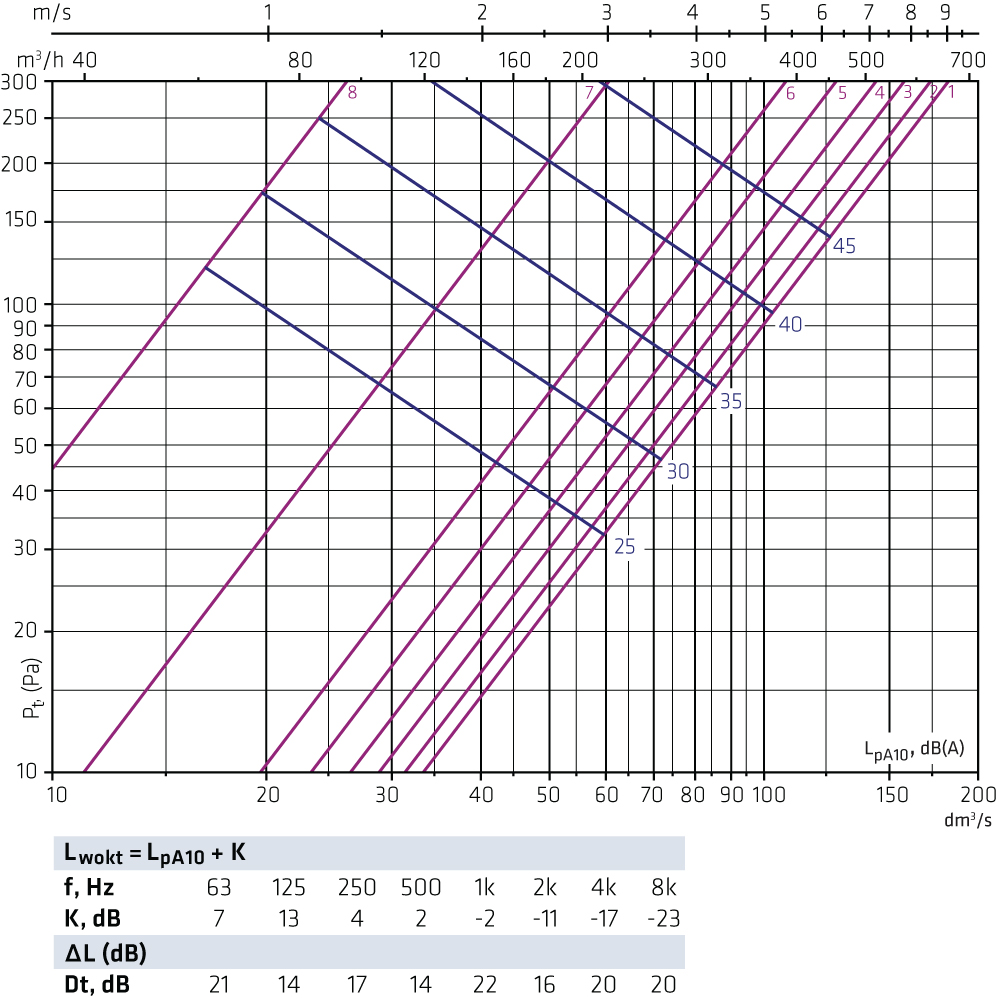
HALOi-200 + FLO-125-200 Exhaust air
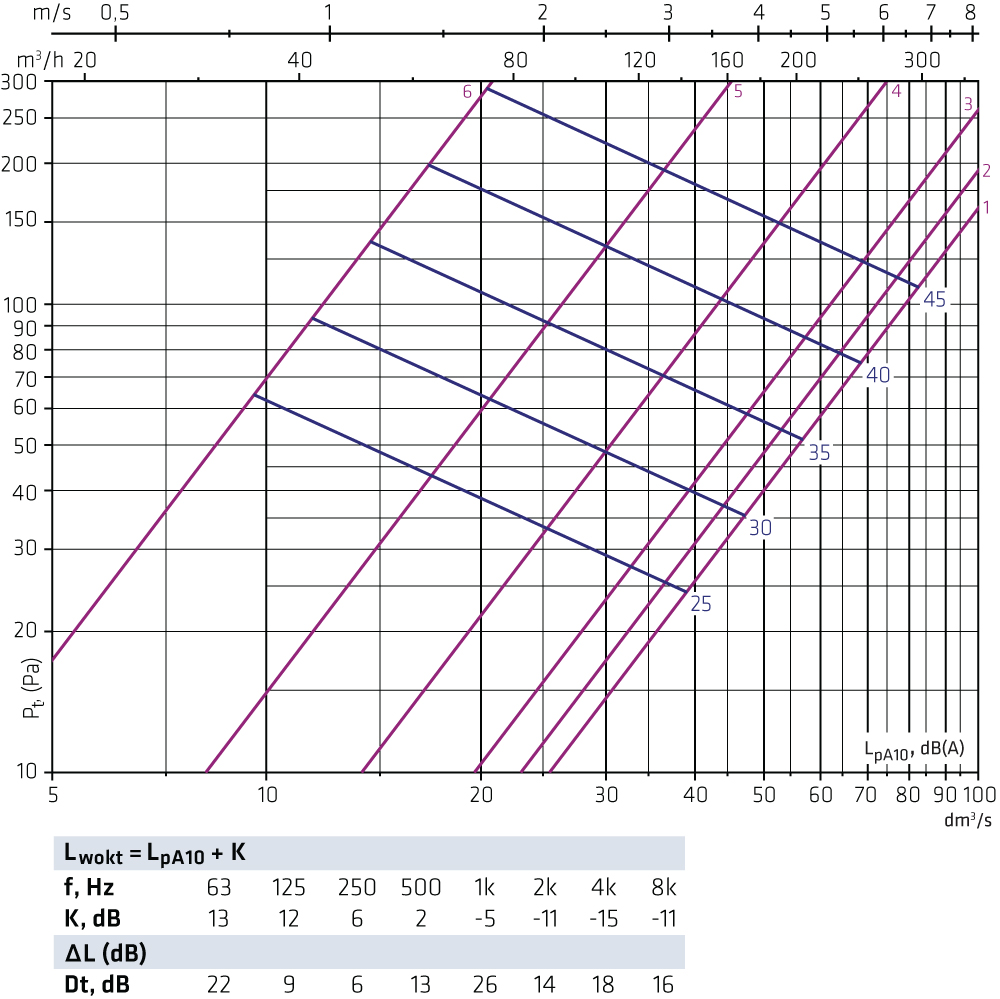
HALOi-200 + FLO-160-200 Exhaust air
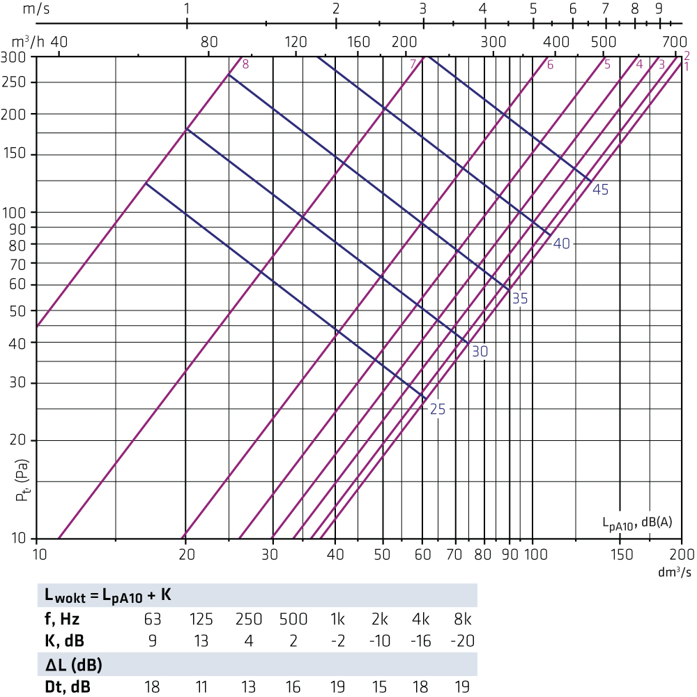
HALOi-200 + FLO-200-200 Exhaust air
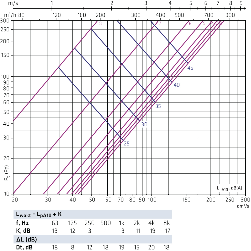
HALOi-250 + FLO-160-250 Exhaust air
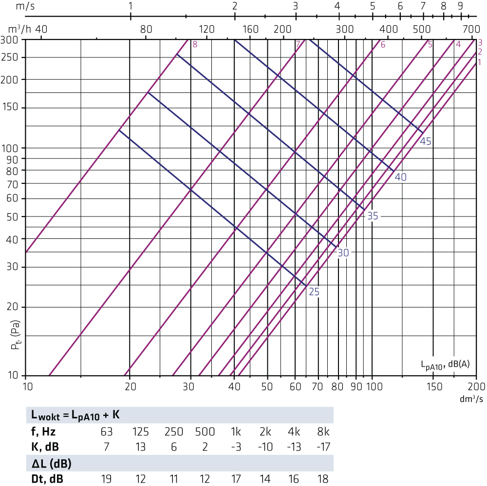
HALOi-250 + FLO-200-250 Exhaust air
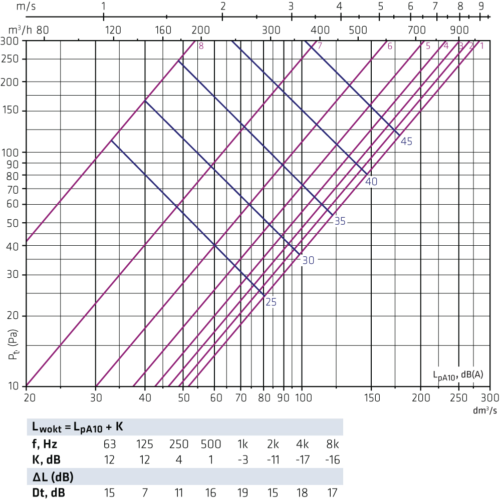
HALOi-250 + FLO-250-250 Exhaust air
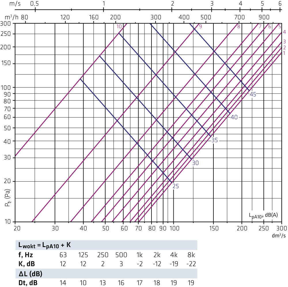
HALOi-315 + FLO-200-315 Exhaust air
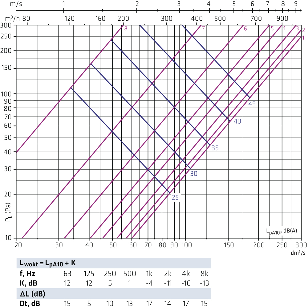
HALOi-315 + FLO-250-315 Exhaust air
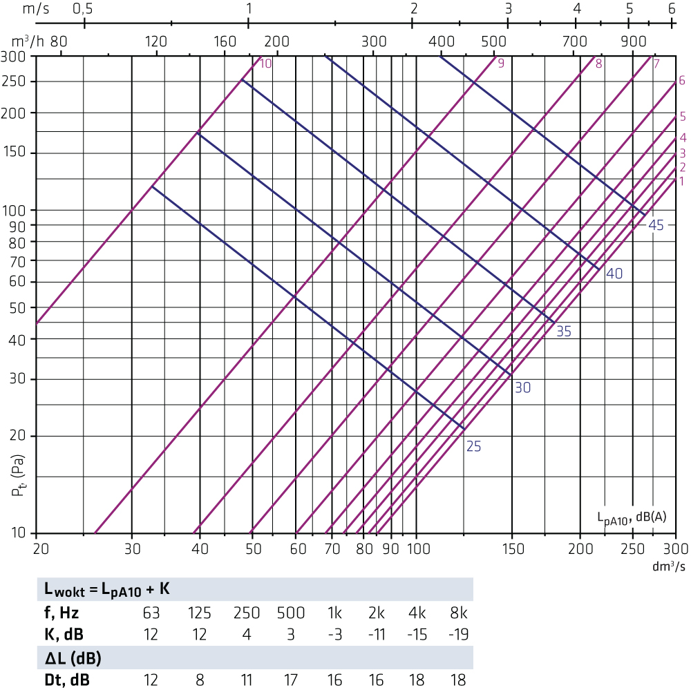
HALOi-315 + FLO-315-315 Exhaust air
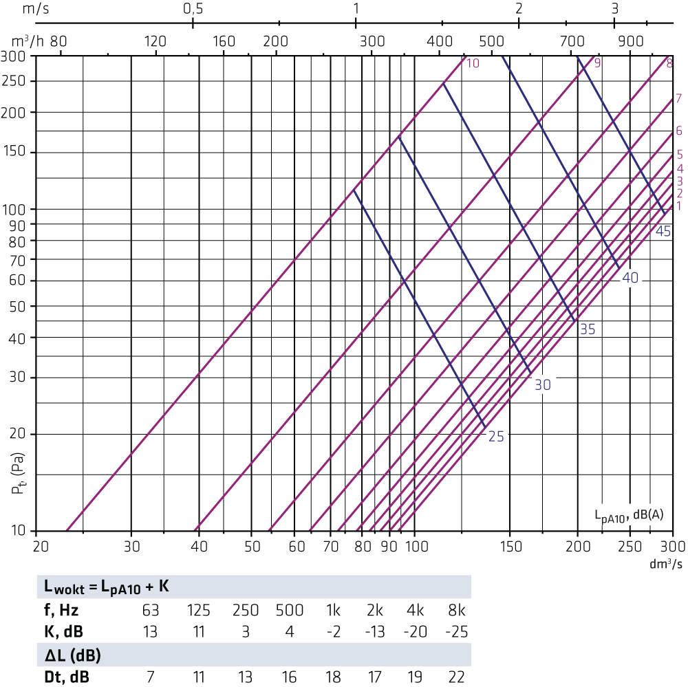
Throw pattern and length
Throw pattern
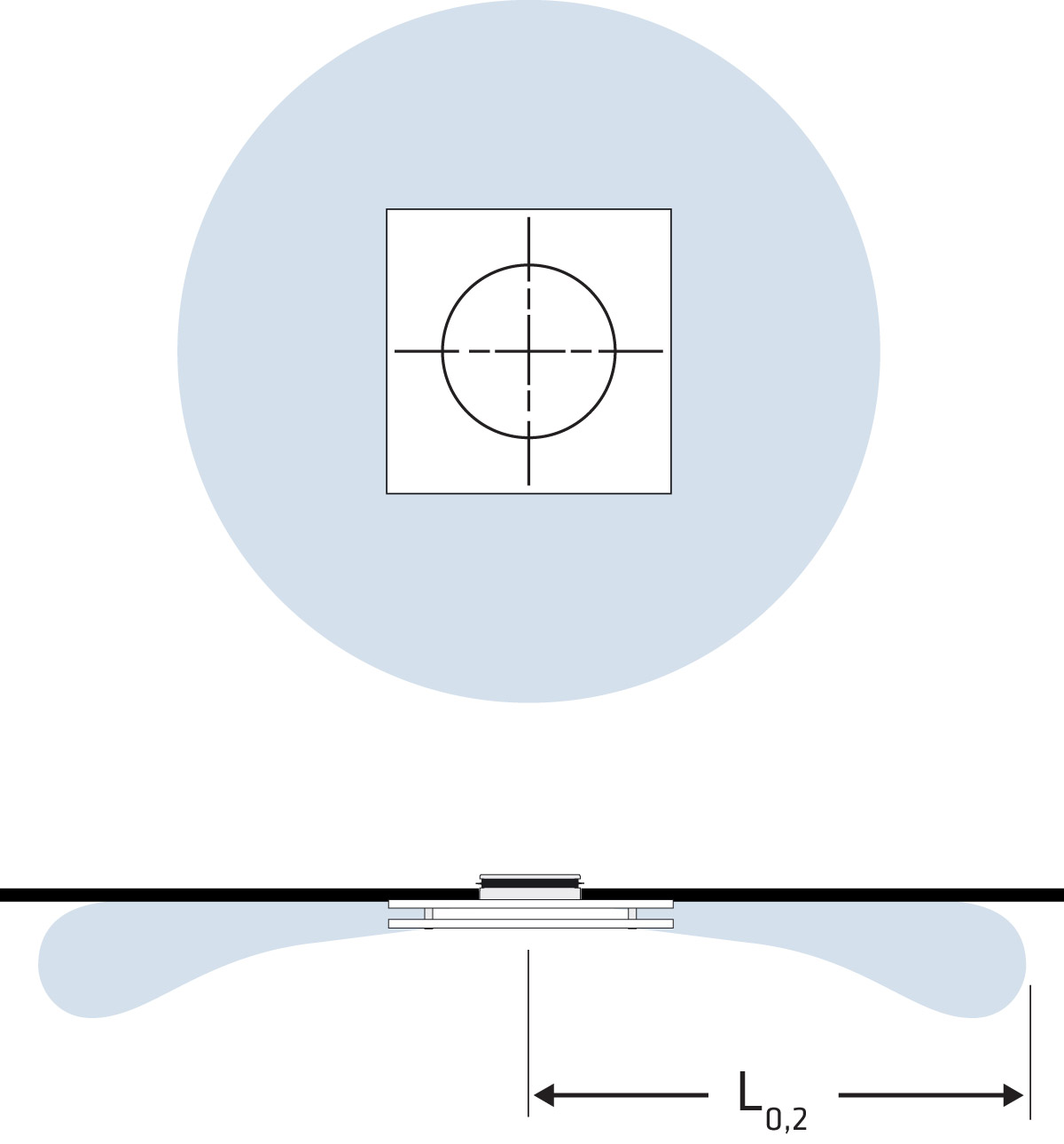
Throw length
4 directions
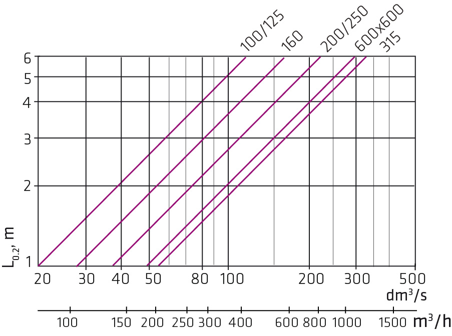
Throw length data values are measured with isothermal supply air.
Airflow is directed at 4 directions, installed against the ceiling without a plenum box.
Factors
No. of directions Throw length L0,2 Sound level dB(A)

The data applies to both HALO models.
We recommend using FLO plenum box for supply air.


