FLO balancing plenum box
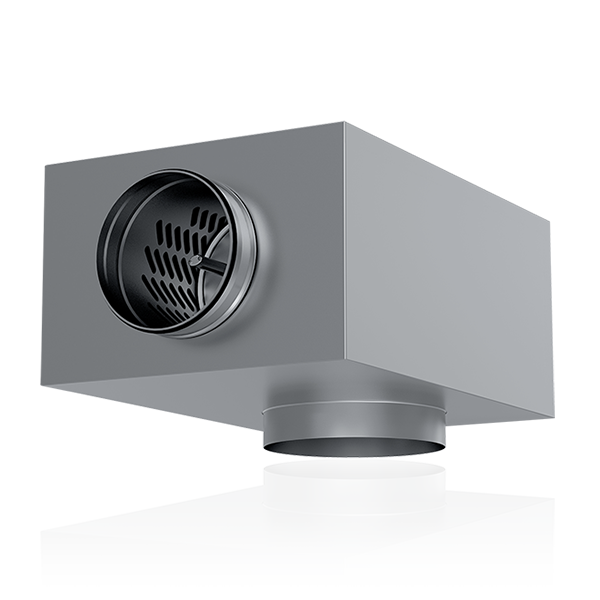
FLO balancing plenum boxFLO is by far the most convenient balancing plenum box on the market. Its groundbreaking SlideFix mechanism makes its adjustment reliable and quick. Low-structured FLO suits both supply and exhaust air and provides outstanding technical features and a wide range of airflow. Measurement accuracy class1 PreadjustedYes SuitabilitySupply and exhaust air Duct sizesØ 100-315 mm DescriptionThe stylish, easy-to-use and reliable FLO balancing plenum box can be used for both supply and exhaust air. The structure of the product is designed to be as low as possible to save space. Despite its compact structure, FLO provides a wide range of airflow and outstanding technical features. Highly accurate air flow measurement (±5%)The device is designed to be easy to install and clean. In addition, the revolutionary SlideFix mechanism locks the chosen adjustment position keeping it unchanged during cleaning or maintenance. Features:
Next generation SlideFix adjustment mechanismThe adjustment of FLO has been made easy with the next generation SlideFix mechanism. The adjustment mechanism of the device is based on pressure differences, which enables the area of air flow to be widened. The excellent flow characteristics of the device have been tested by VTT.
Highly accurate adjustmentFLO adjustment accuracy is proven to fulfill the requirements of airflow measurement class 1 performance. This means that the air volumes remain in between 5% of that designed even during performance, installation or maintenance. Accurate adjustment and performance are critical when designing a high-quality and controlled ventilation system. The highly precise airflow measurement is reached by measuring pressure difference across the adjustment unit and by enabling a broad adjustment range. SlideFix adjustment locking mechanism offers a robust and effortless way to adjust the devices. The devices can be pre-adjusted using values set in MagiCAD or Revit. Preadjusted devices are aesier and quicker to manage during adjustment and installation phases. Quick guideFLO + OLE
FLO + OLOi
FLO + OLO
FLO + REK/LEK Exhaust air
FLO + REK/LEK Supply air
FLO + ILO
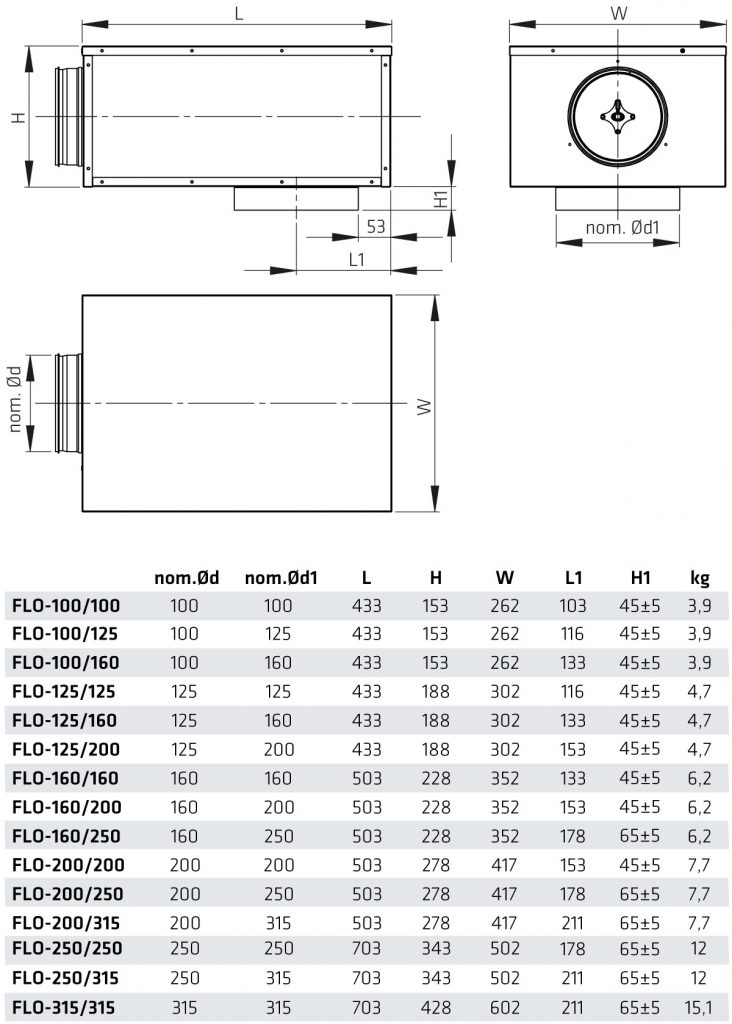
Dimensions
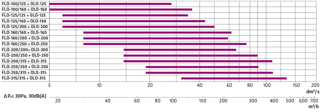
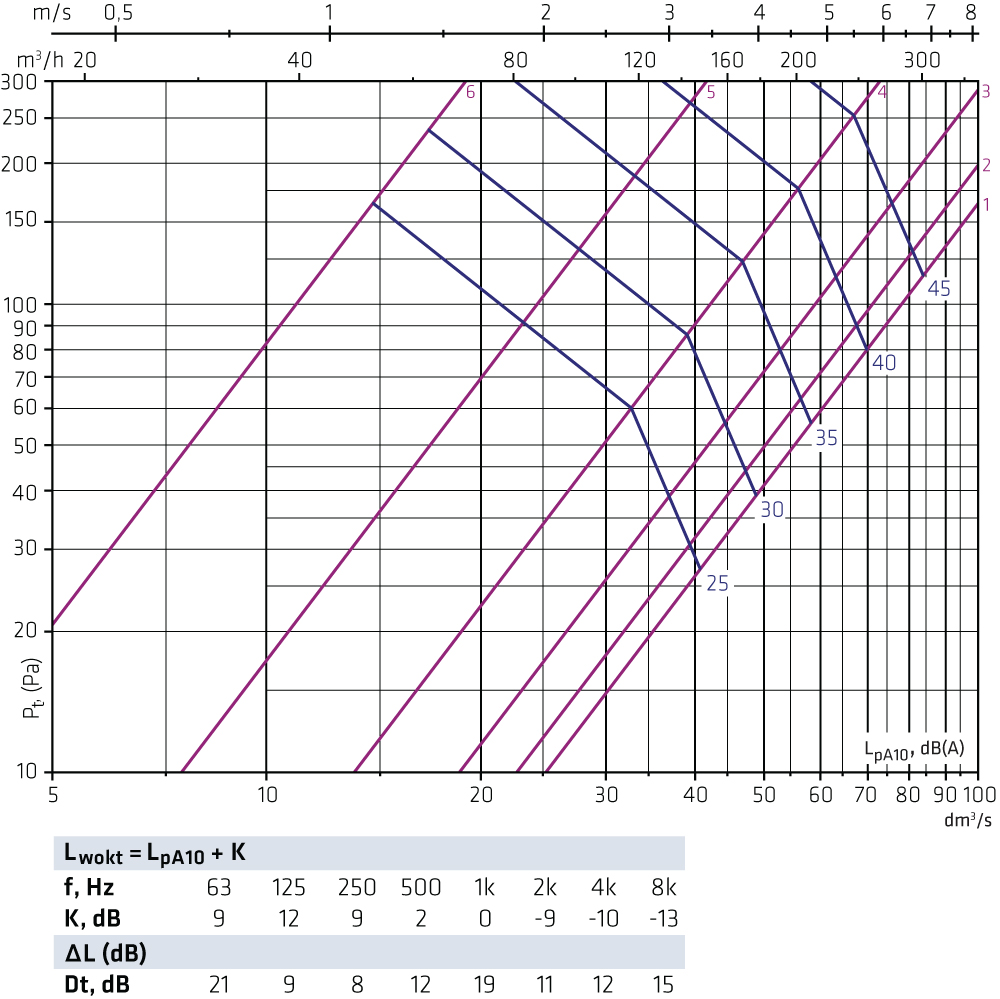
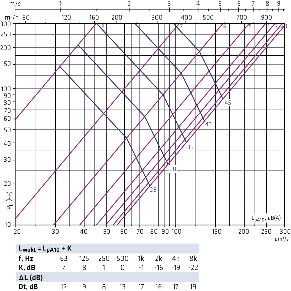
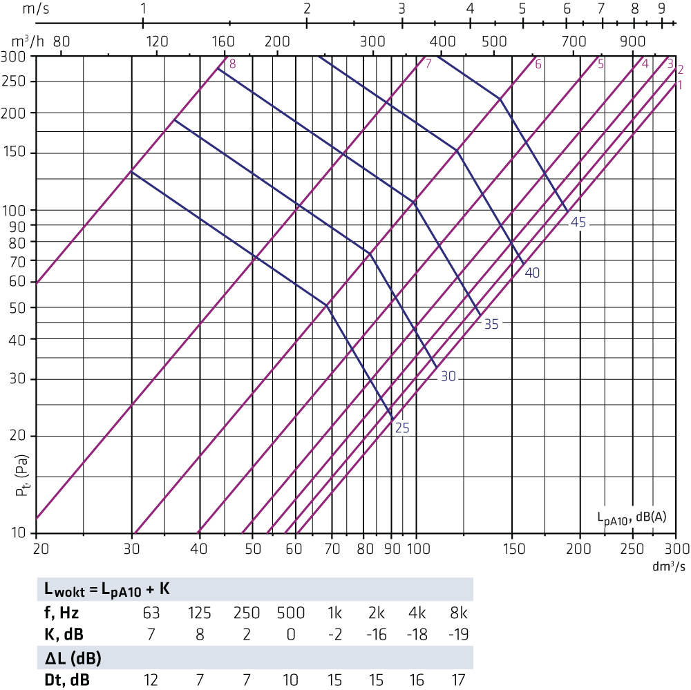
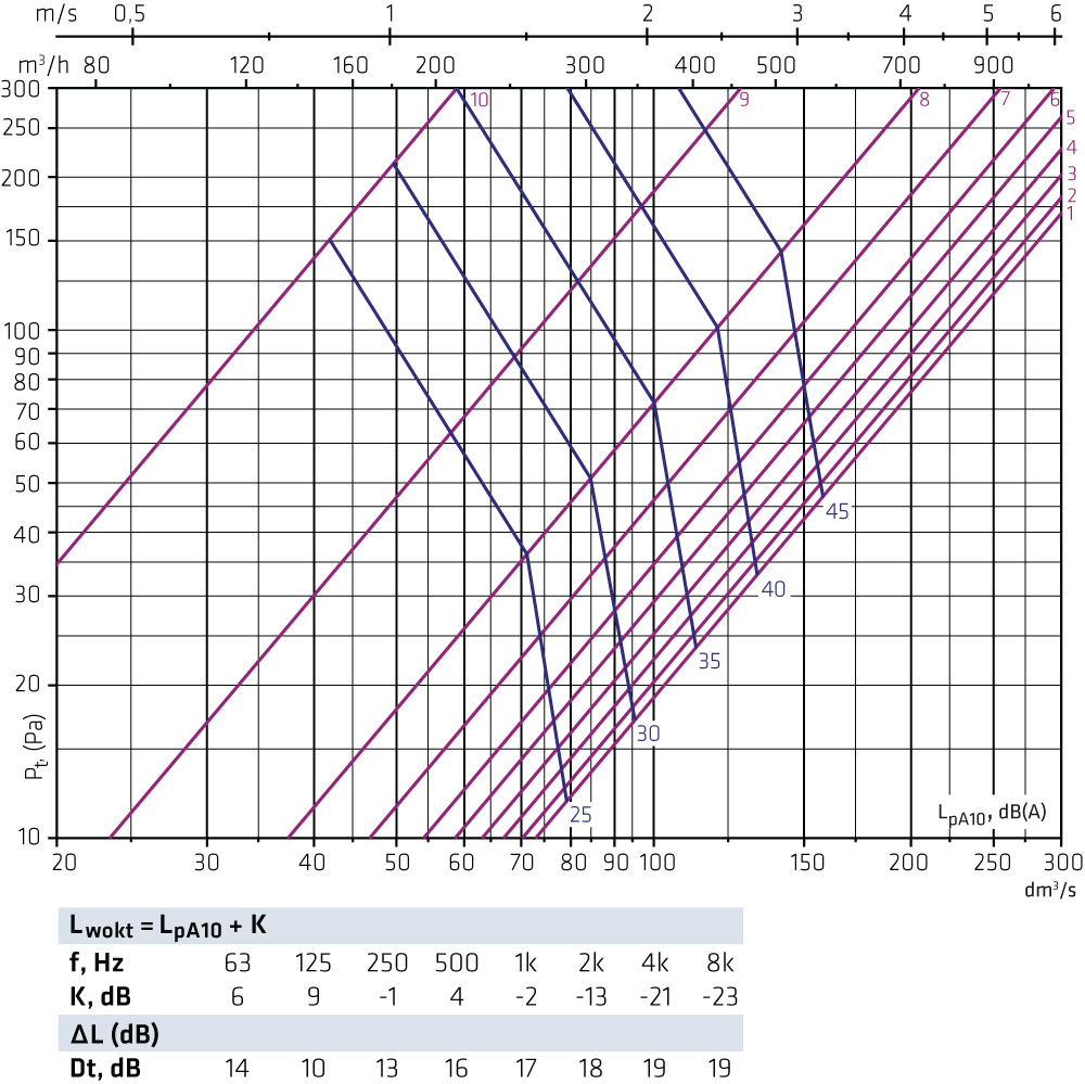
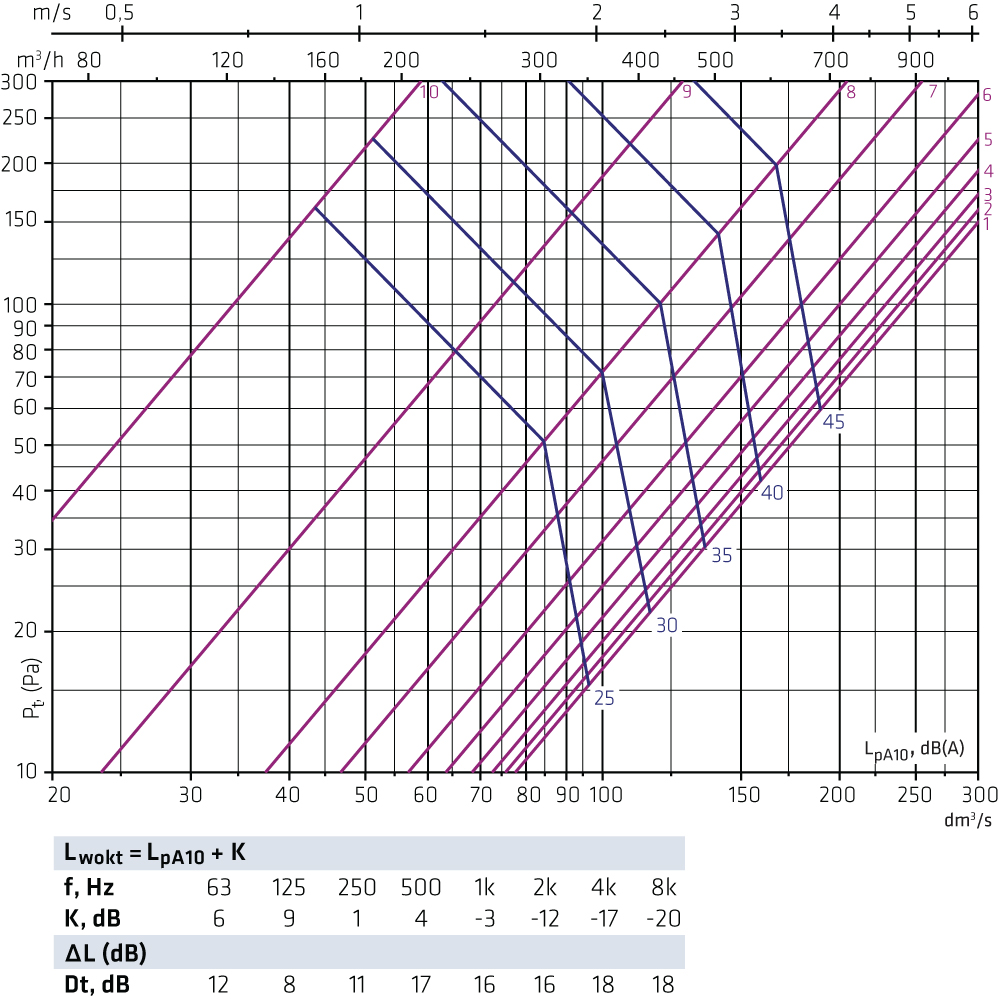
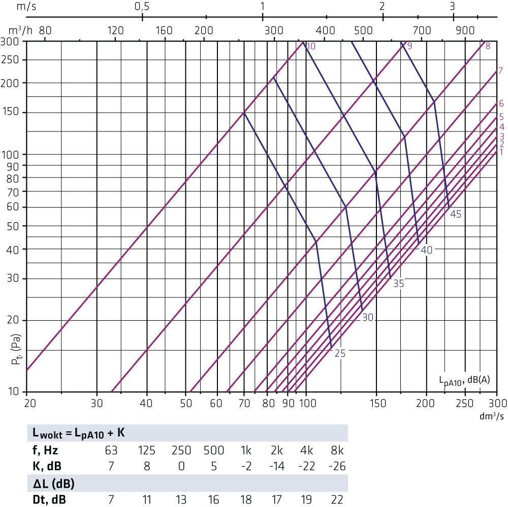
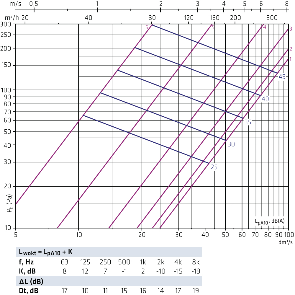
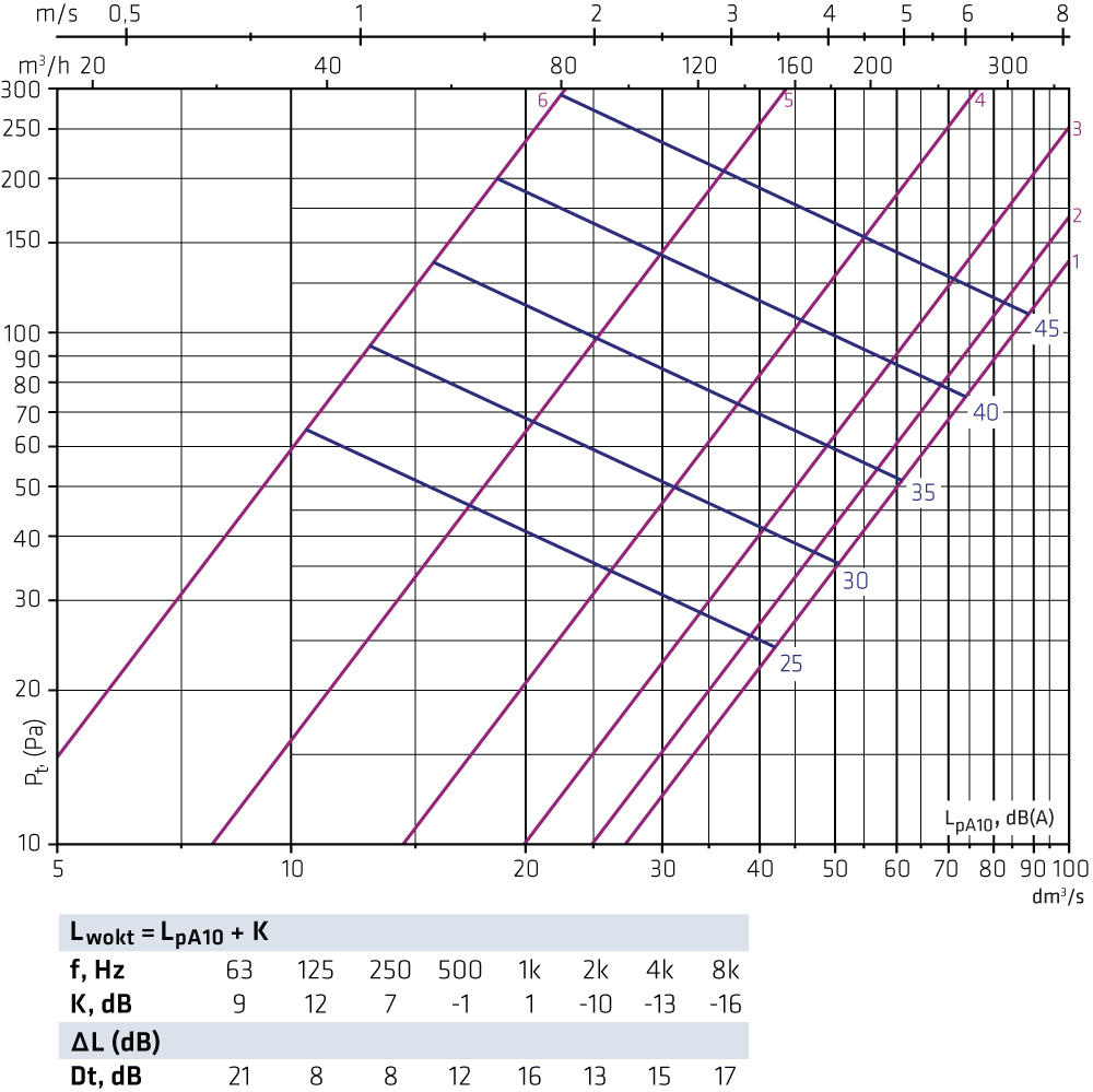
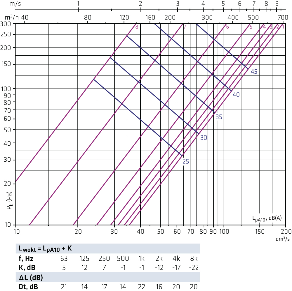
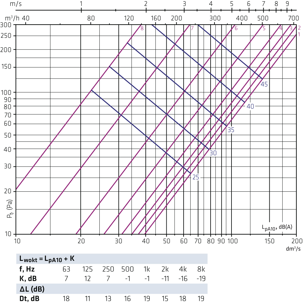
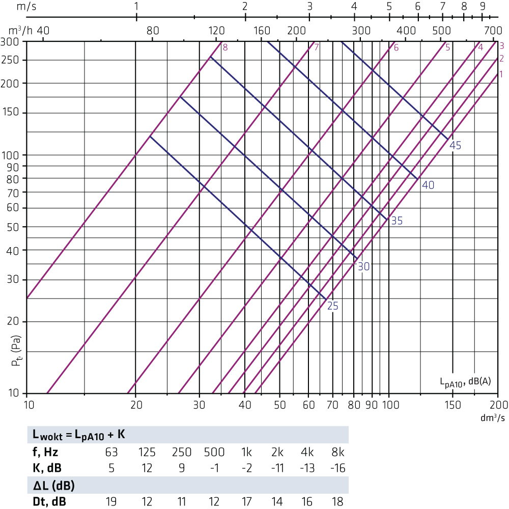
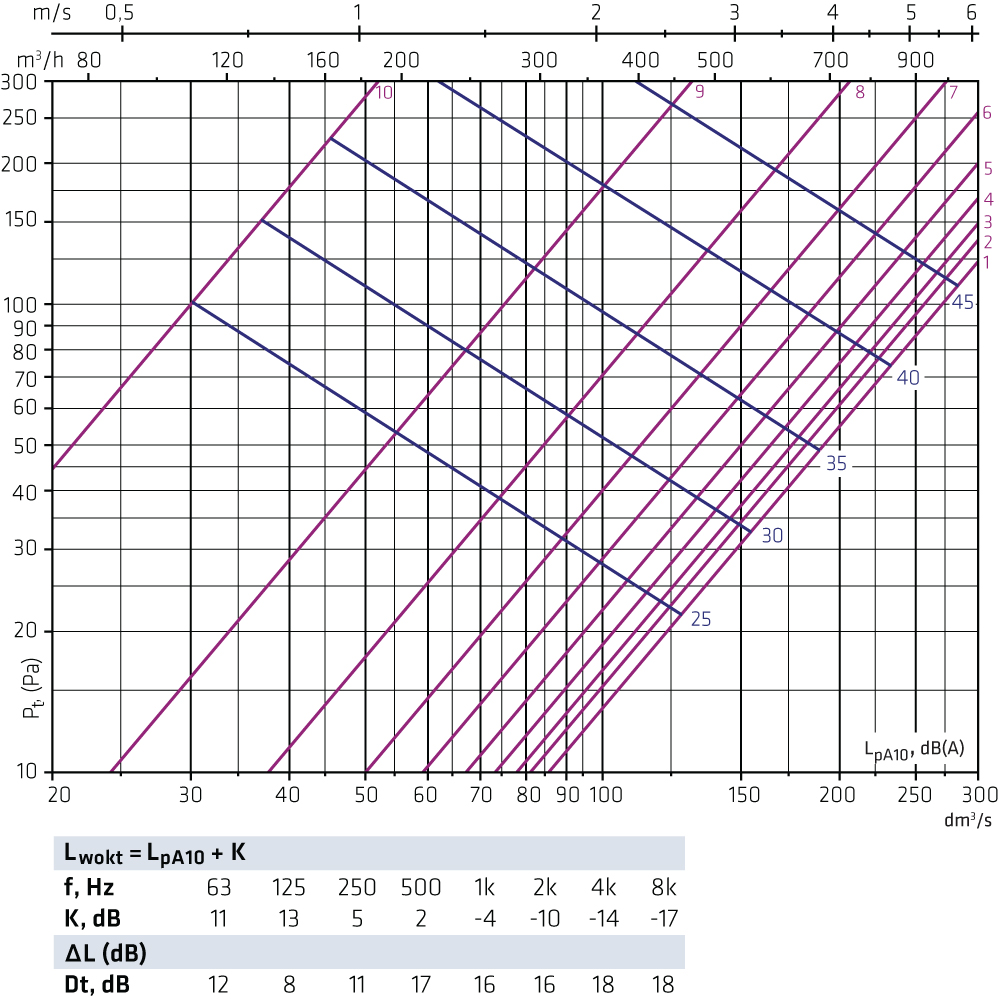
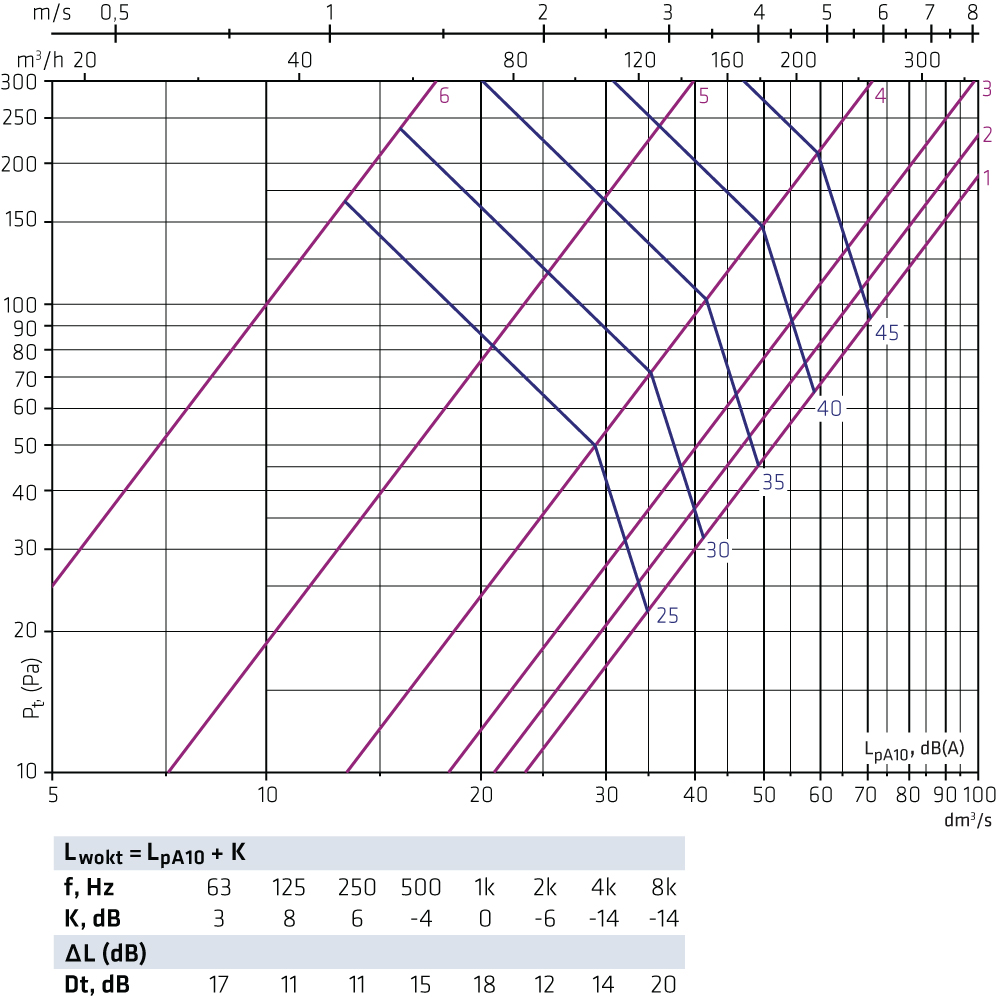
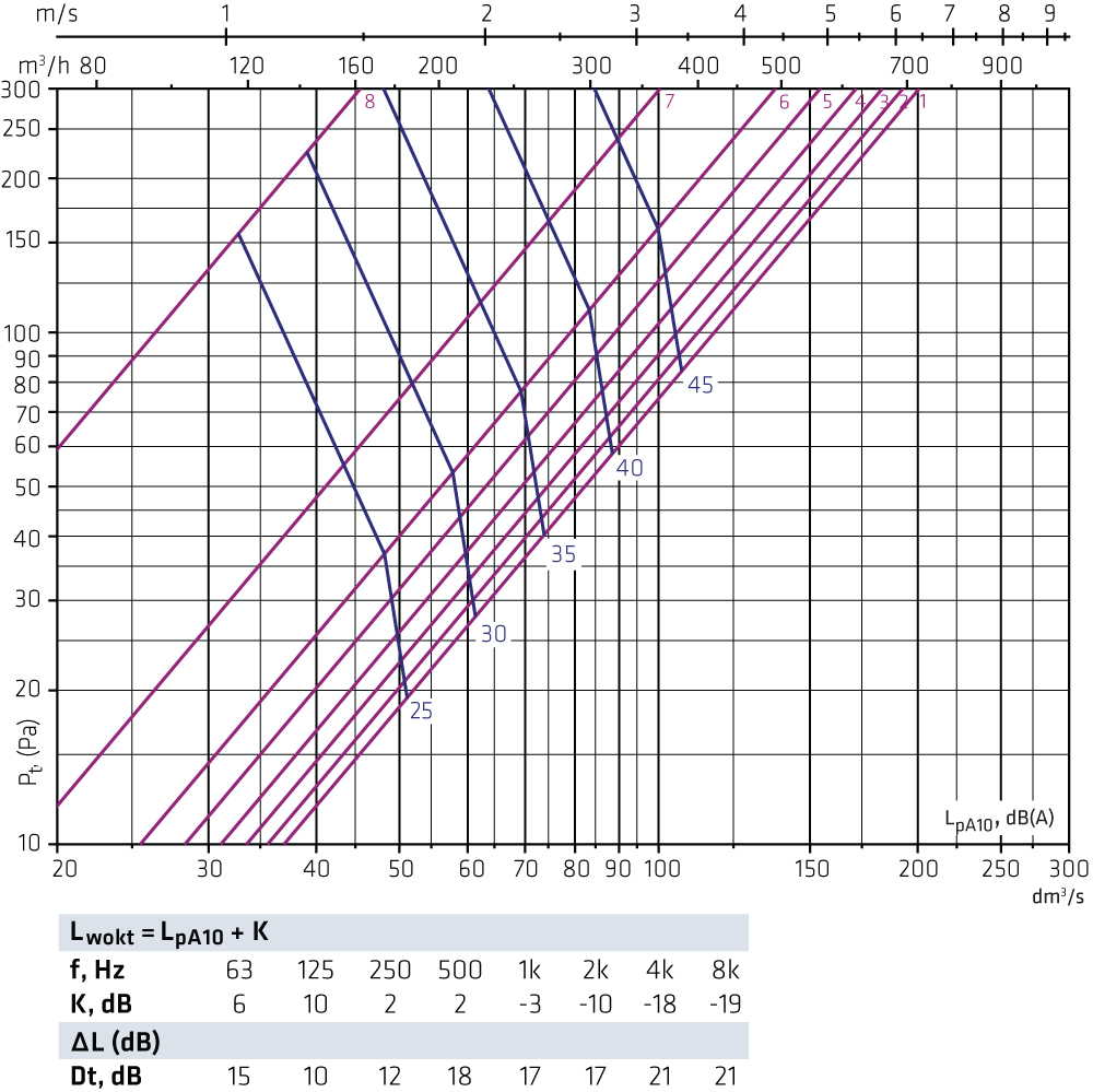
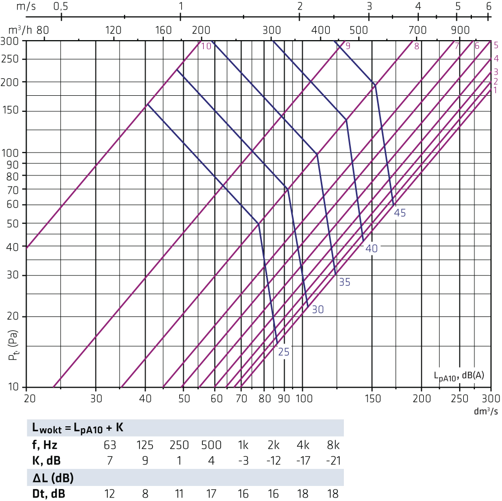
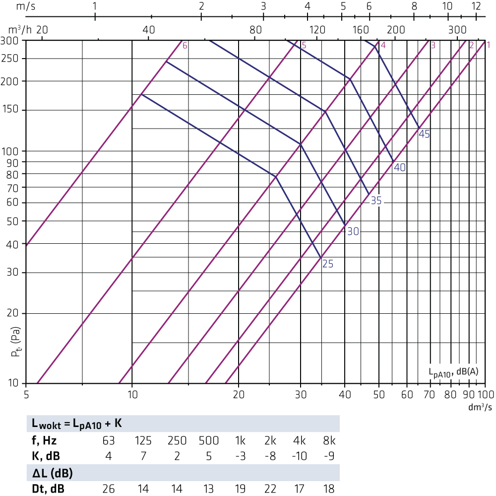
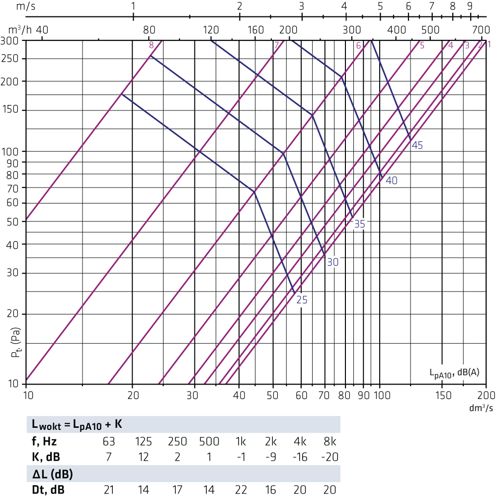
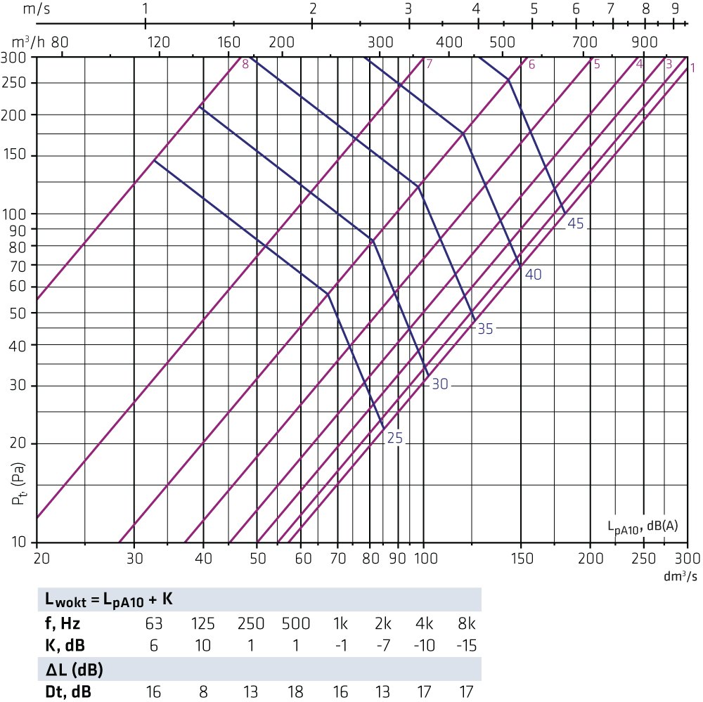
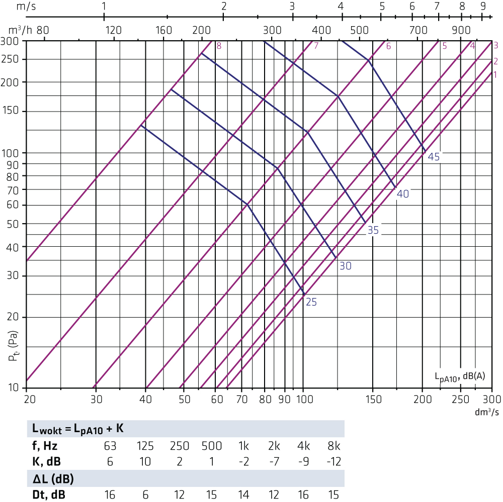
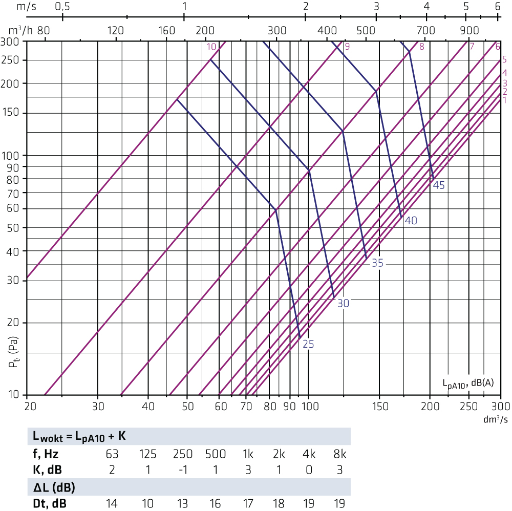
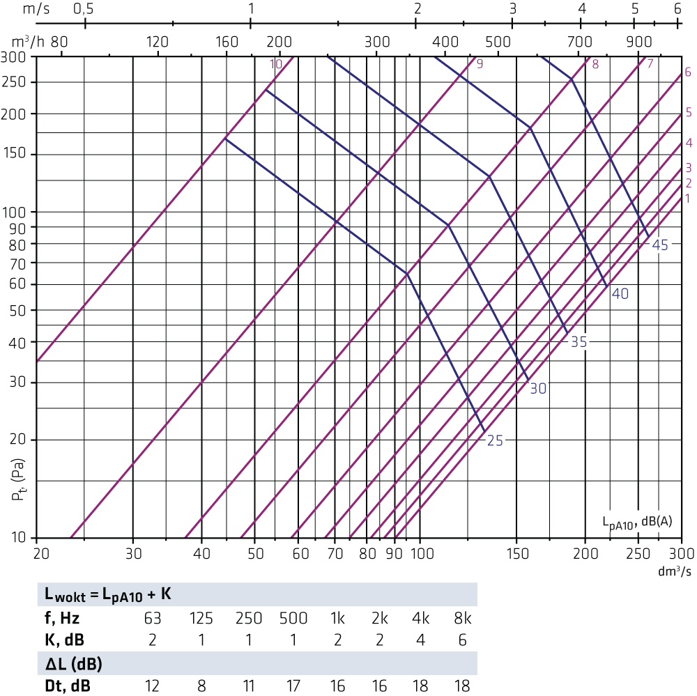
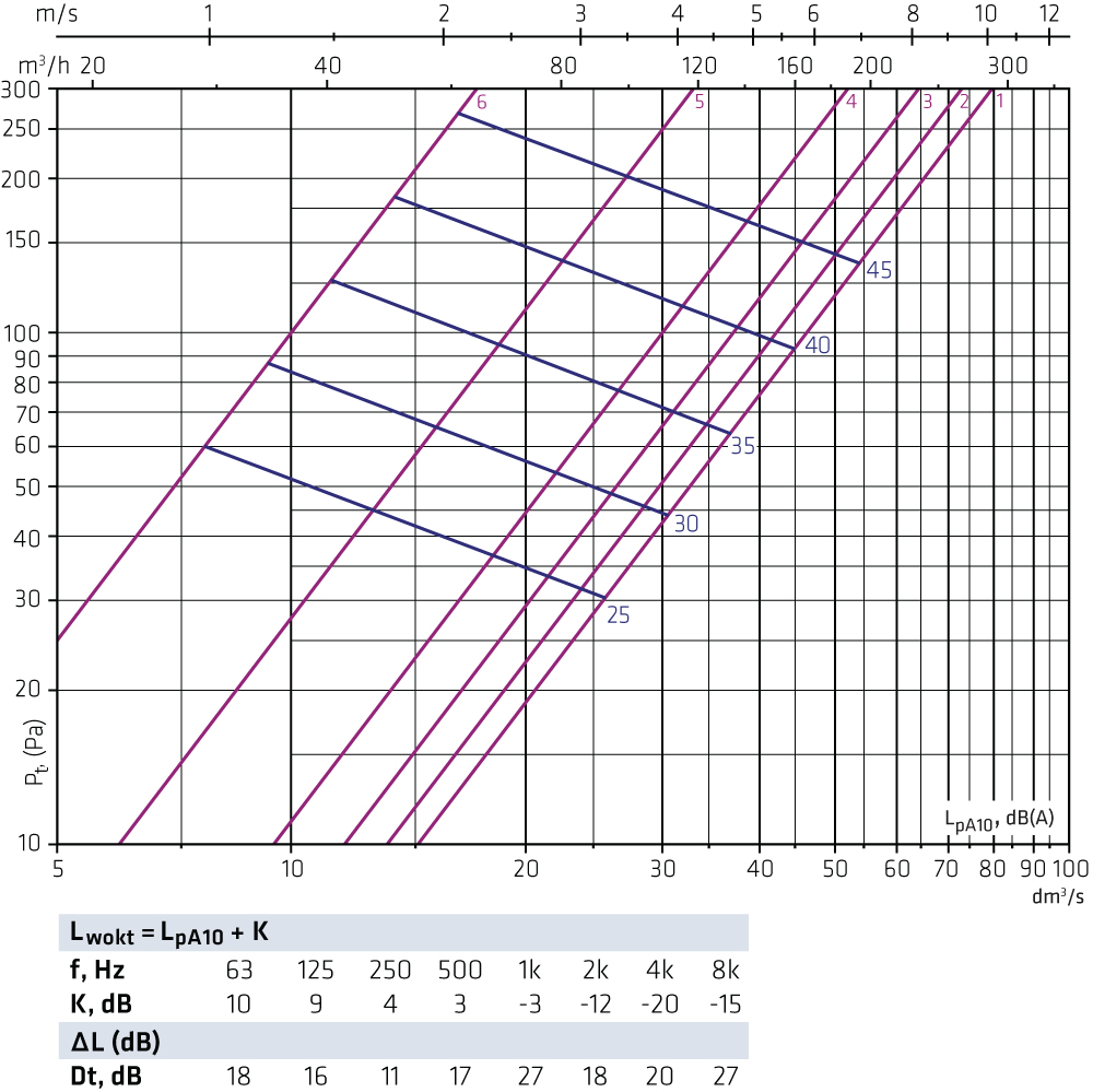
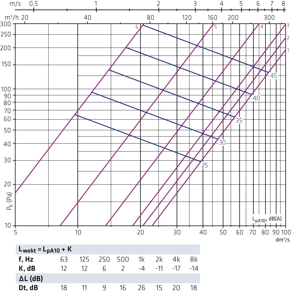
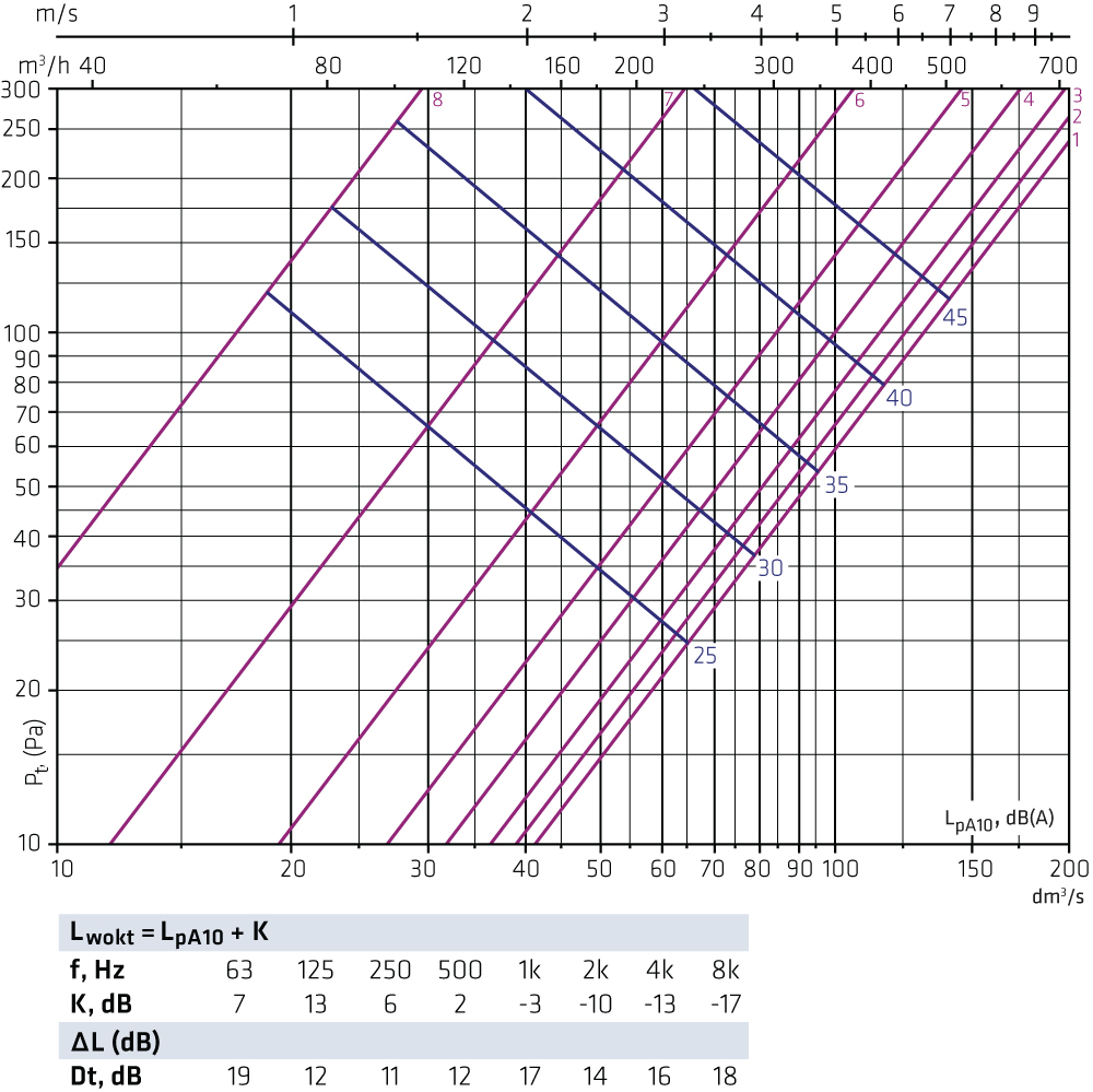
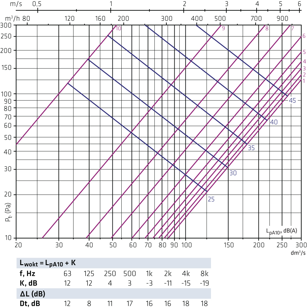
Selection diagrams FLO + OLOThe graphs are not intended for adjusting. FLO-100-125 + OLO-125 Supply air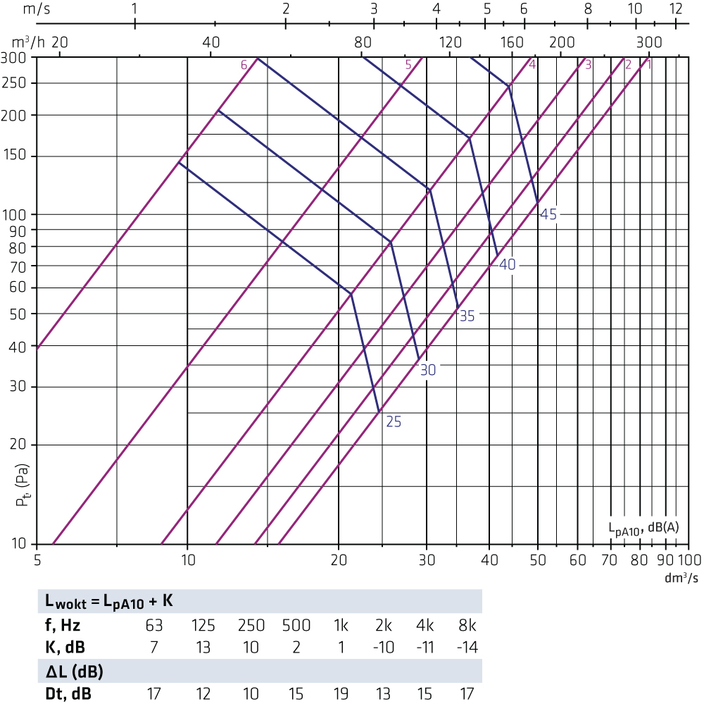 FLO-100-160 + OLO-160 Supply air
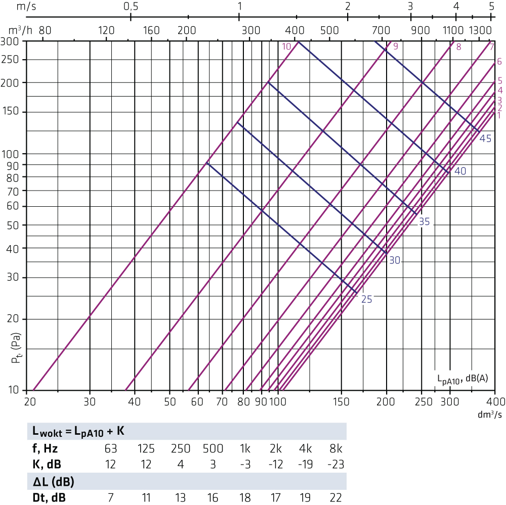
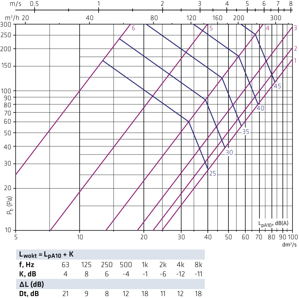
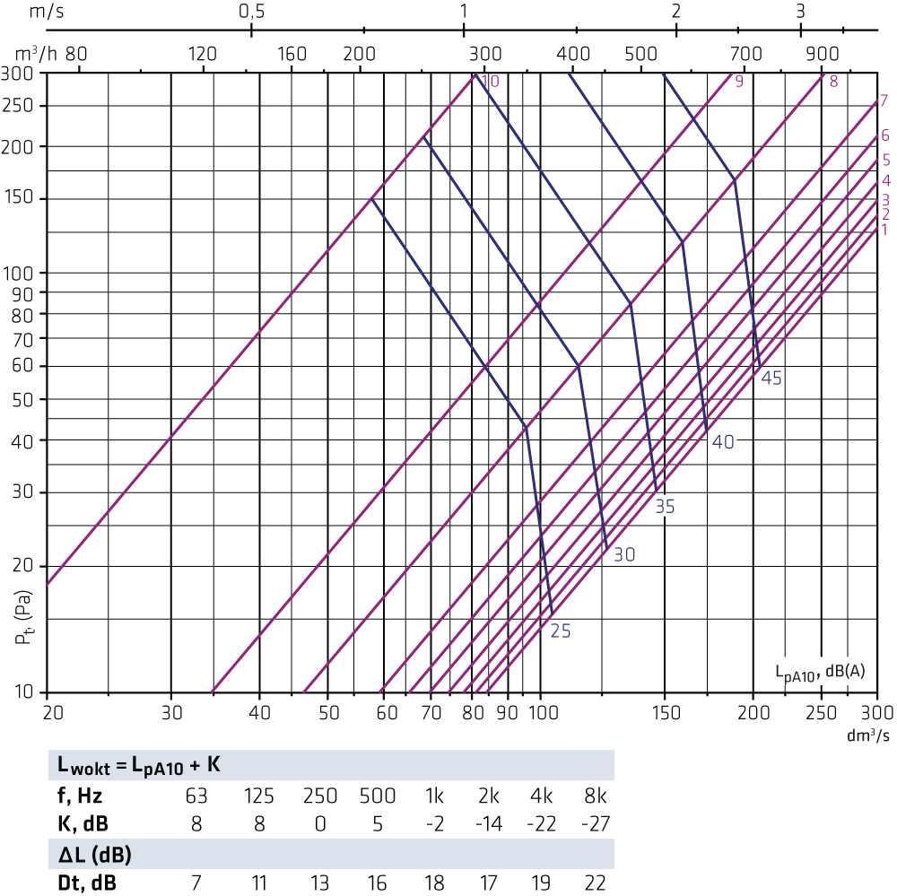
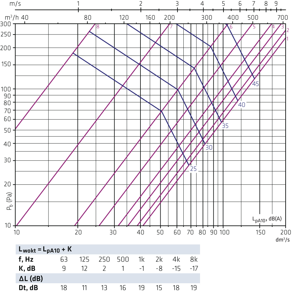
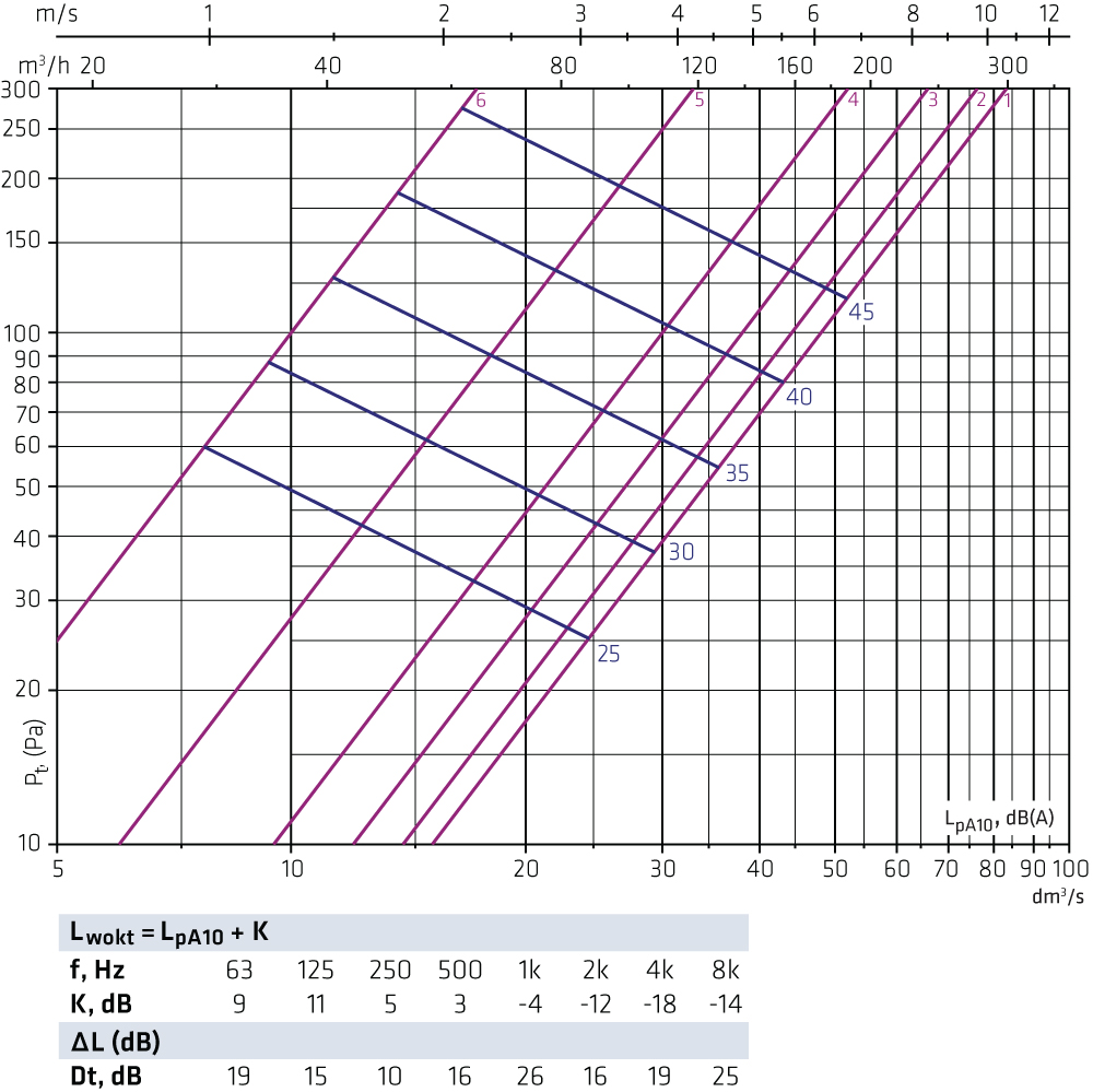
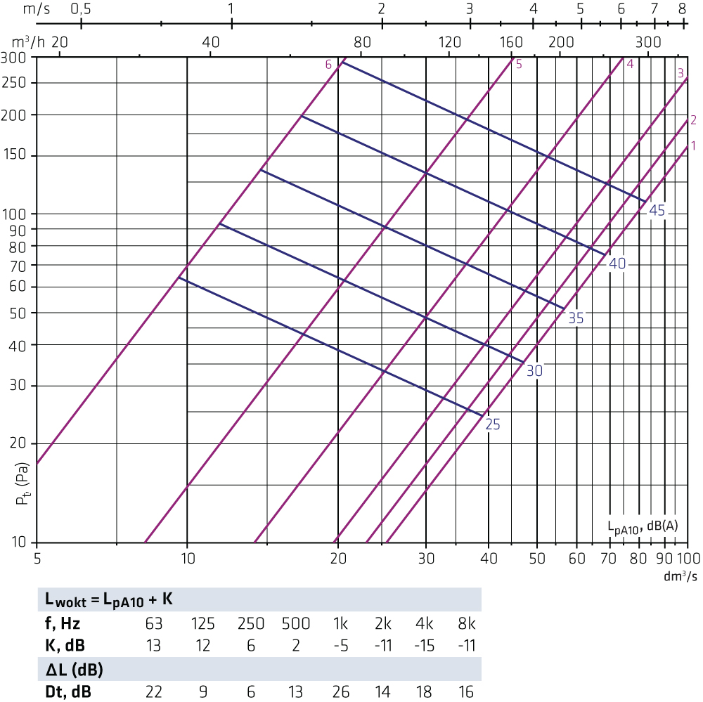
FLO-125-125 + OLO-125 Supply air
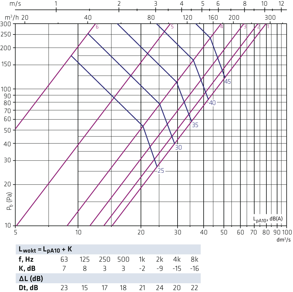
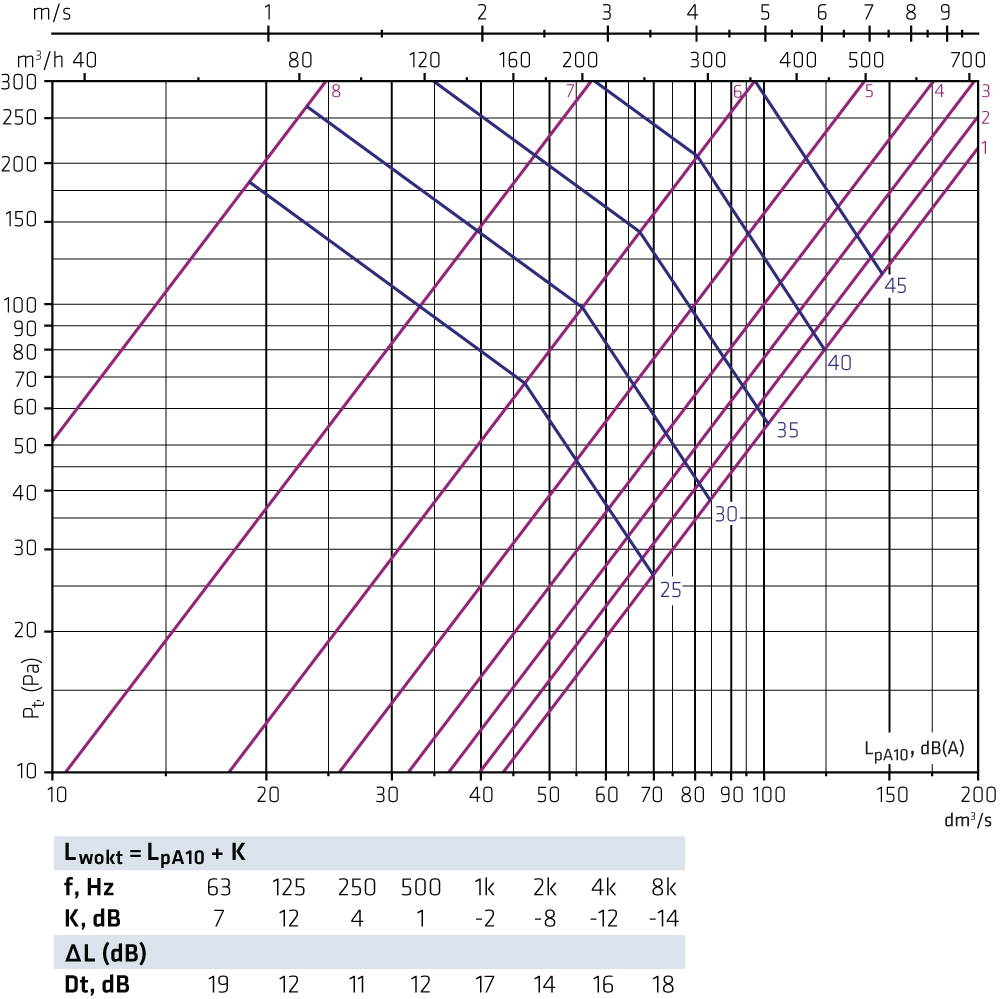
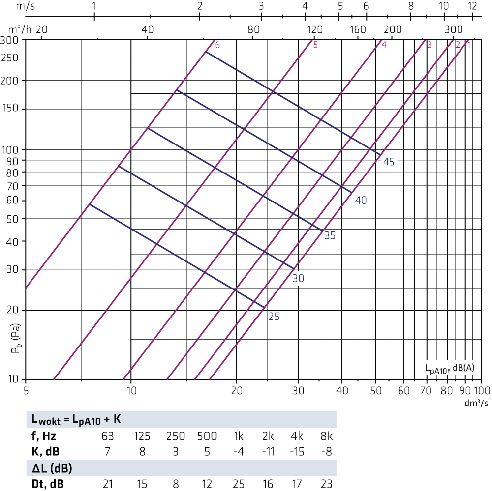
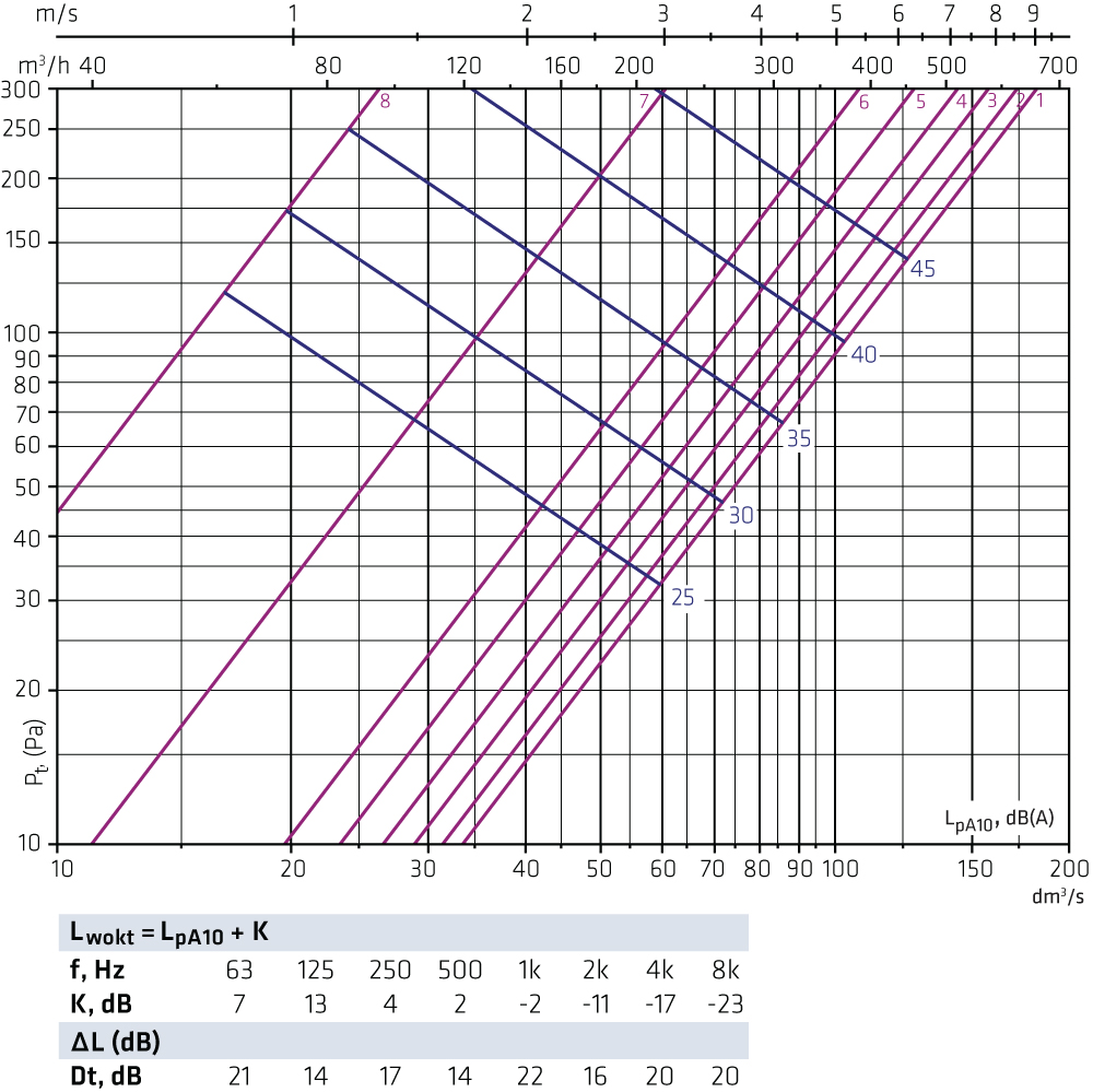
FLO-125-160 + OLO-160 Supply air
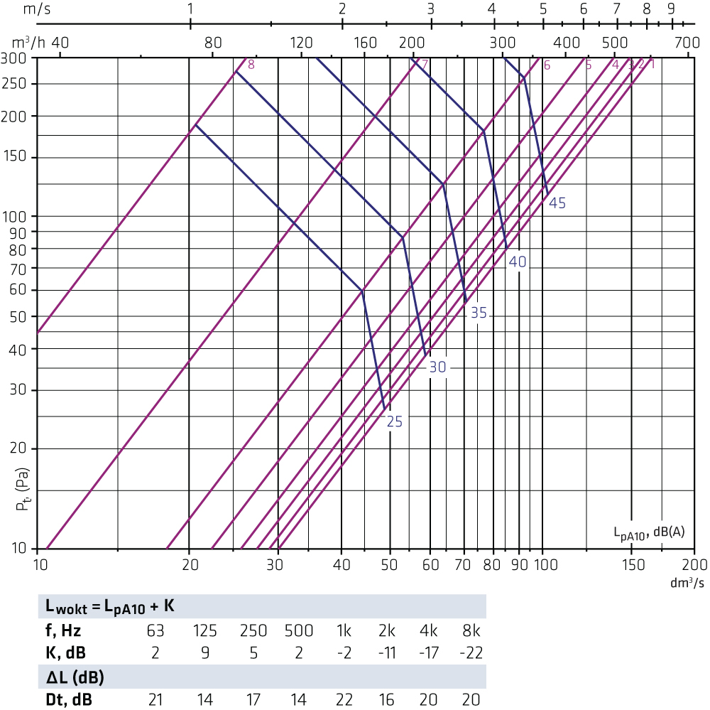
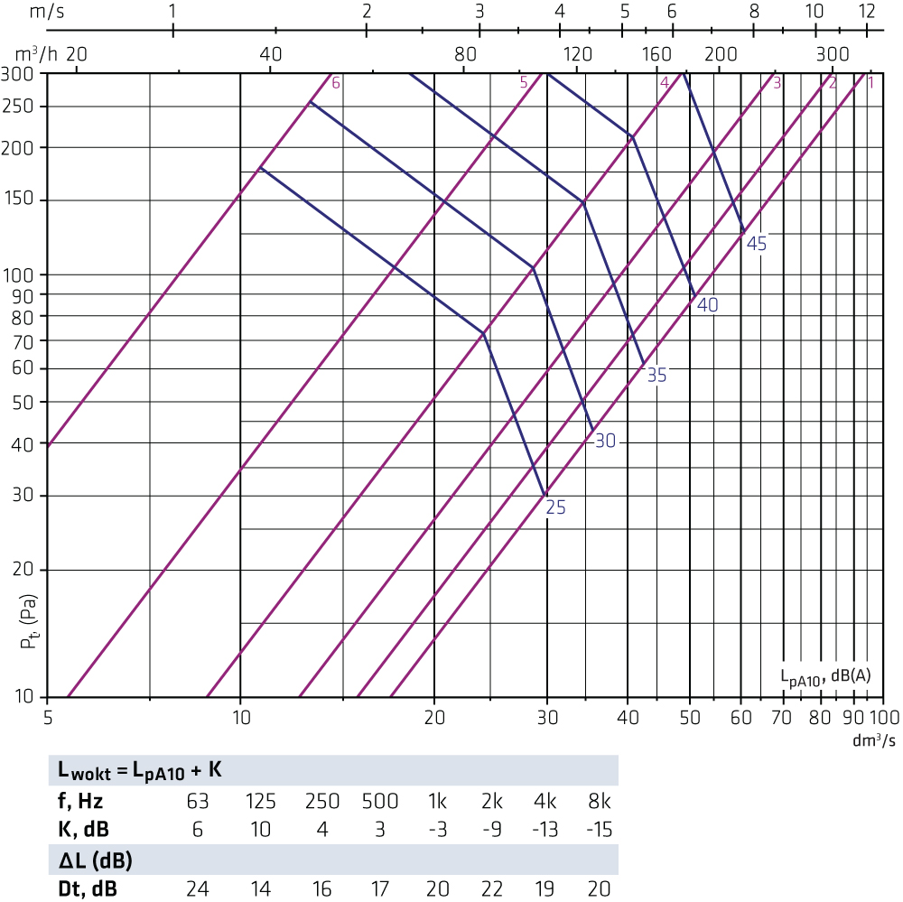
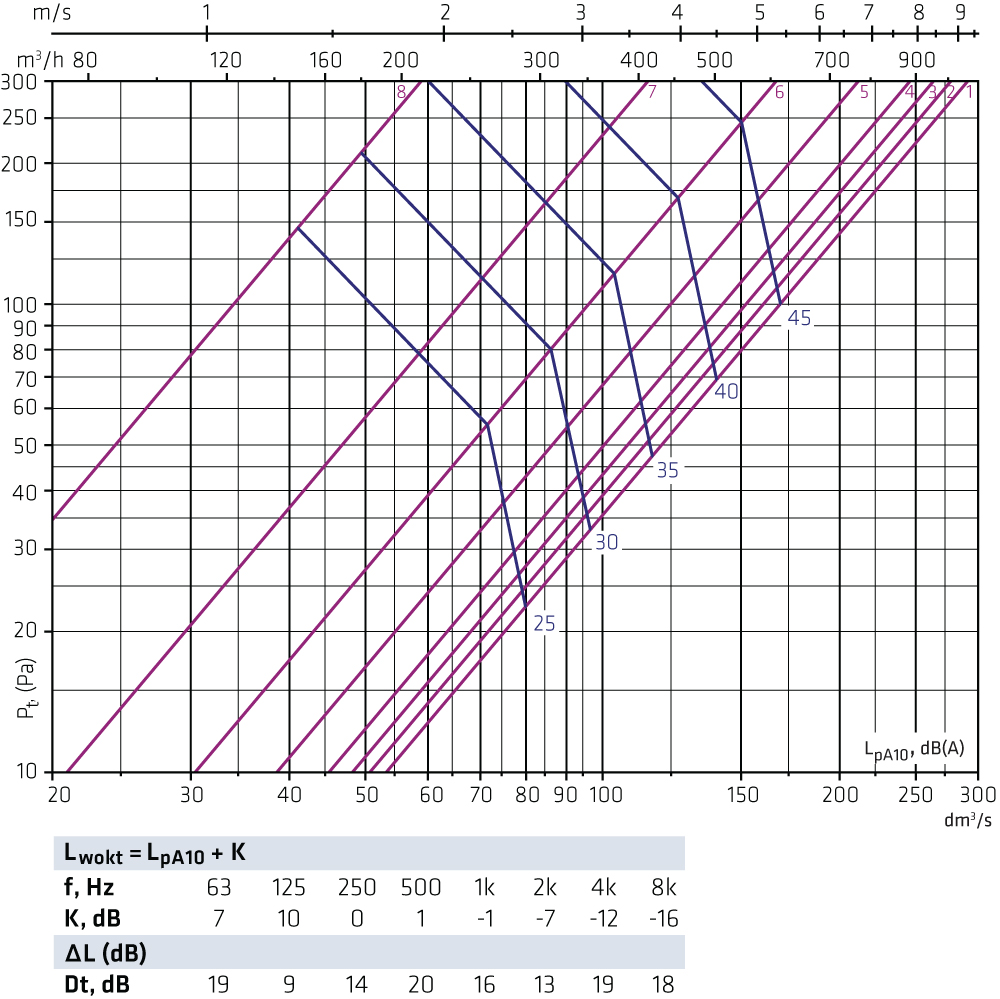
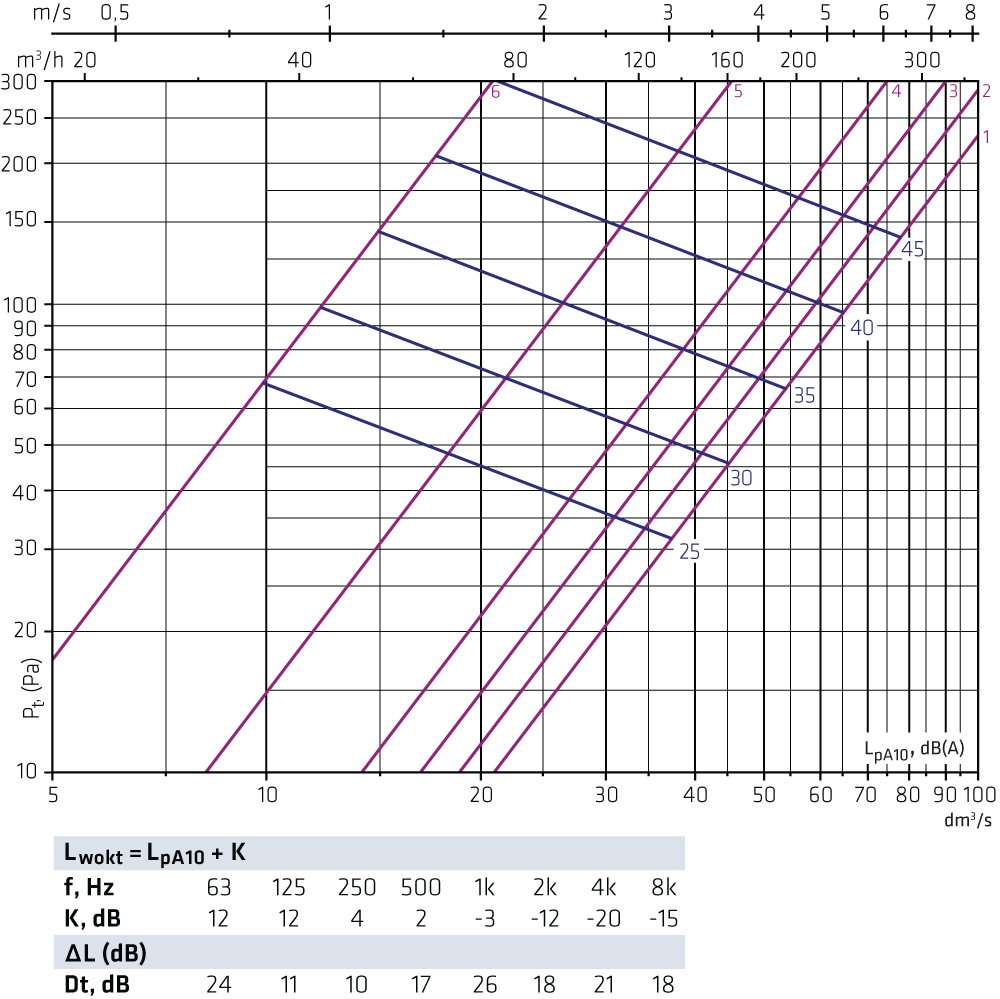
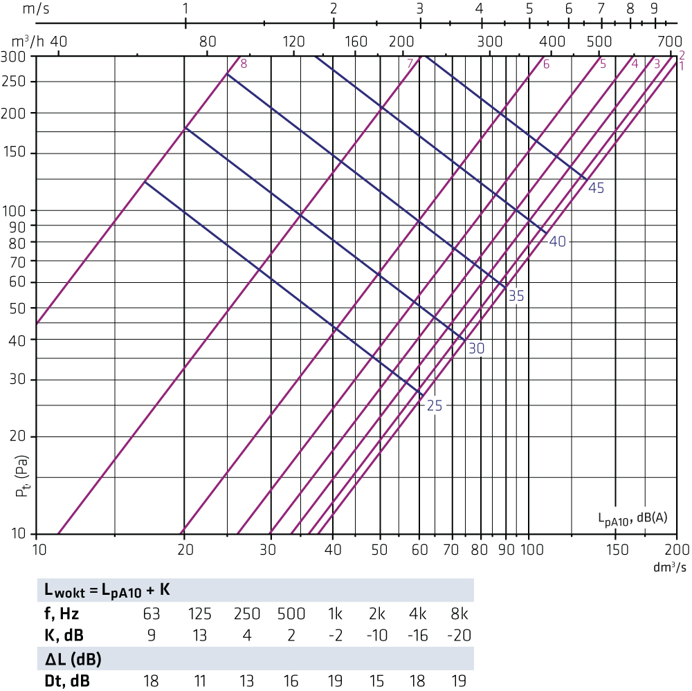
FLO-125-200 + OLO-200 Supply air
FLO-160-160 + OLO-160 Supply air
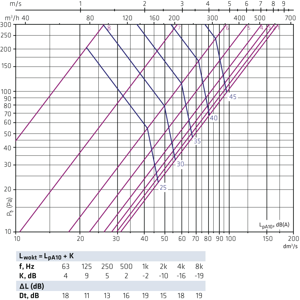
FLO-160-200 + OLO-200 Supply air
FLO-160-250 + OLO-250 Supply air
FLO-200-200 + OLO-200 Supply air
FLO-200-250 + OLO-250 Supply air
FLO-200-315 + OLO-315 Supply air
FLO-250-250 + OLO-250 Supply air
FLO-250-315 + OLO-315 Supply air
FLO-315-315 + OLO-315 Supply air
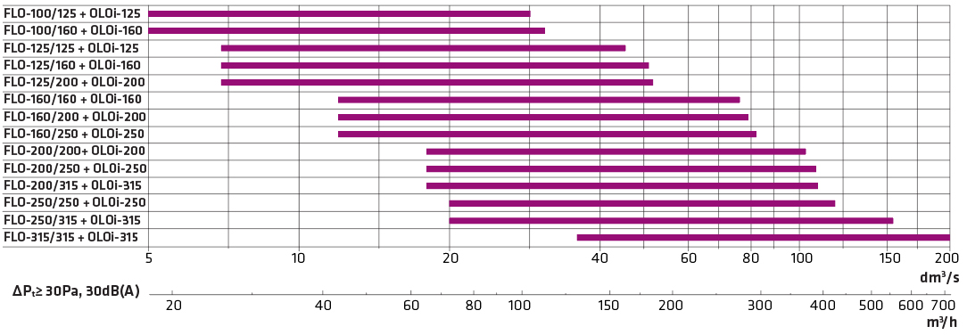
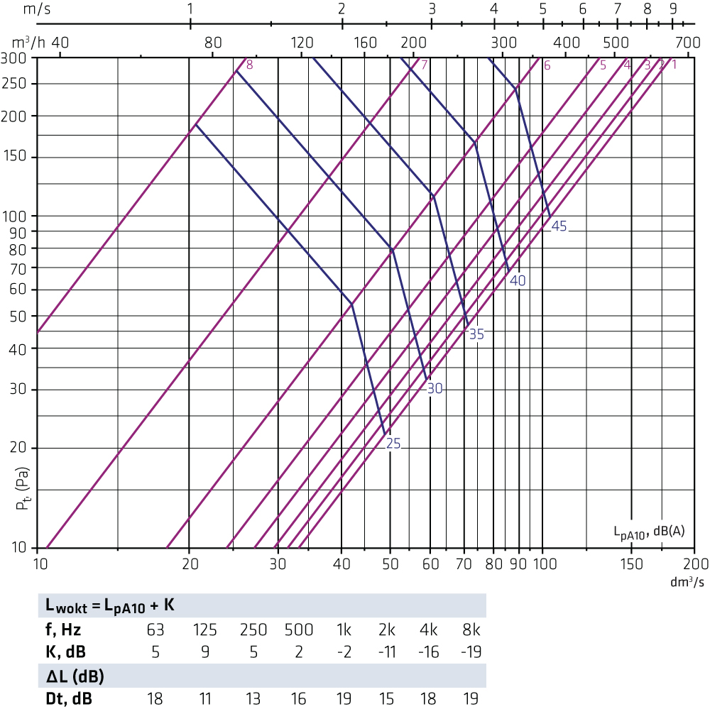
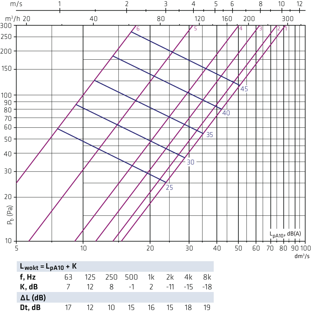
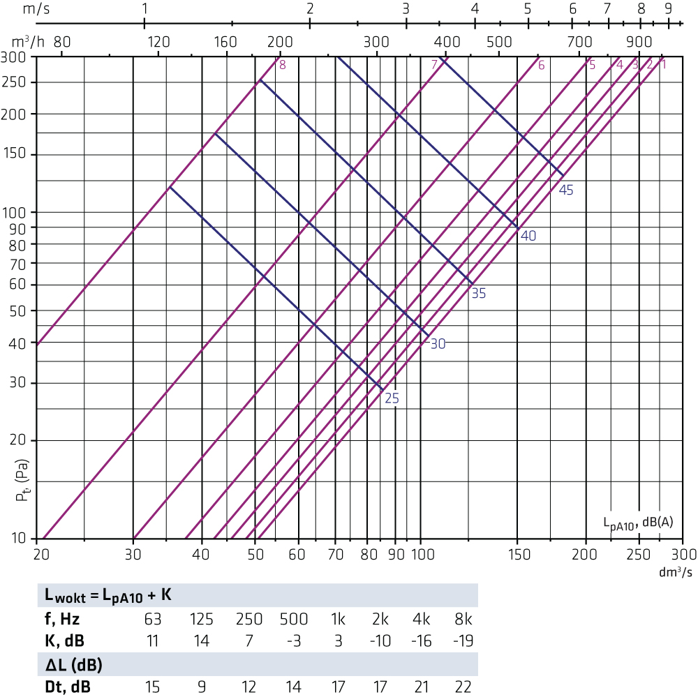
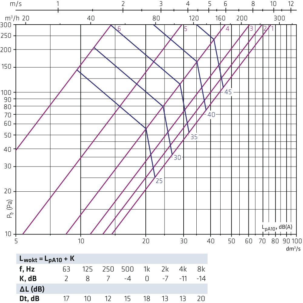
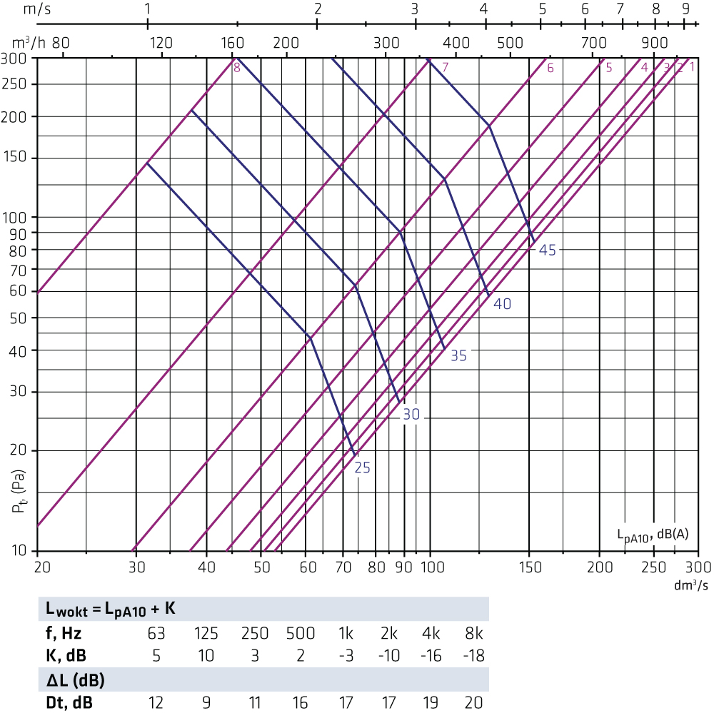
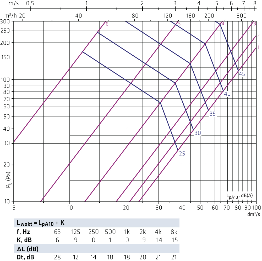
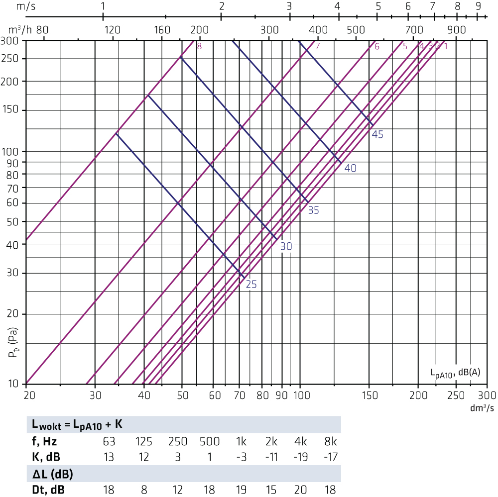
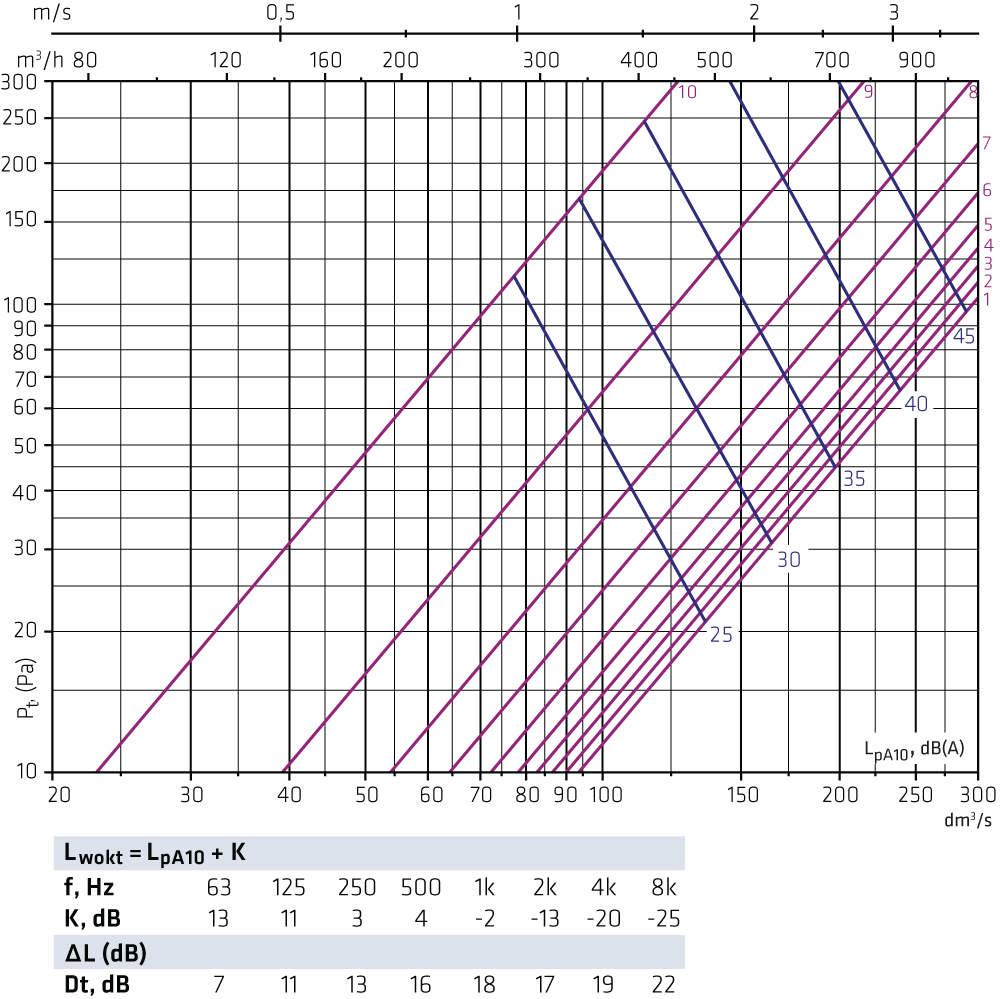
Selection diagrams FLO + OLOiThe graphs are not intended for adjusting. FLO-100-125 + OLOi-125 Exhaust air
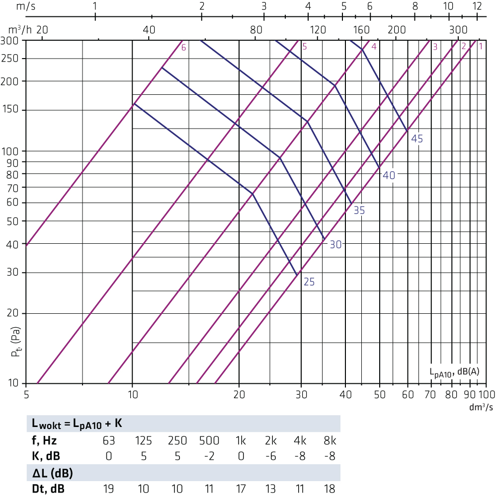
FLO 100-160 + OLOi 160 Exhaust air
FLO-125-125 + OLOi-125 Exhaust air
FLO-125-160 + OLOi-160 Exhaust air
FLO-125-200 + OLOi-200 Exhaust air
FLO-160-160 + OLOi-160 Exhaust air
FLO-160-200 + OLOi-200 Exhaust air
FLO-160-250 + OLOi-250 Exhaust air
FLO-200-200 + OLOi-200 Exhaust air
FLO-200-250 + OLOi-250 Exhaust air
FLO-200-315 + OLOi-315 Exhaust air
FLO-250-250 + OLOi-250 Exhaust air
FLO-250-315 + OLOi-315 Exhaust air
FLO-315-315 + OLOi-315 Exhaust air
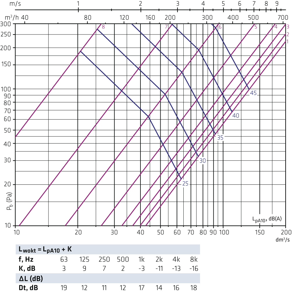
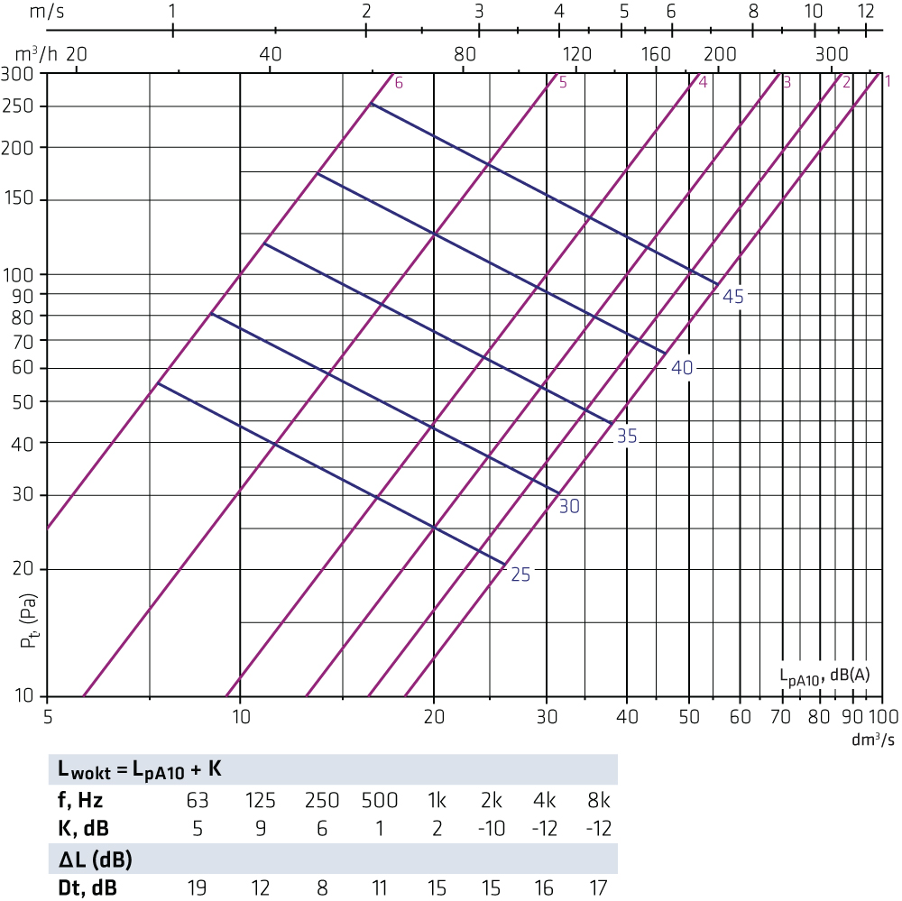
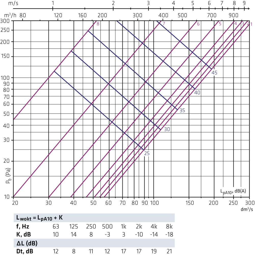
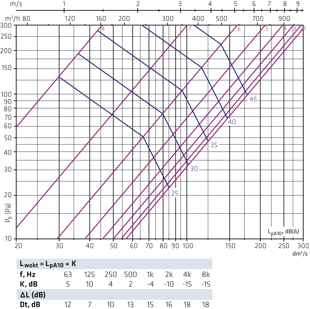
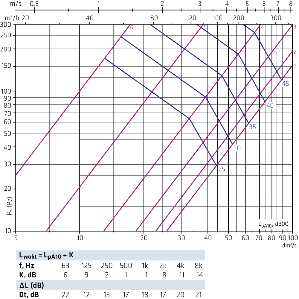
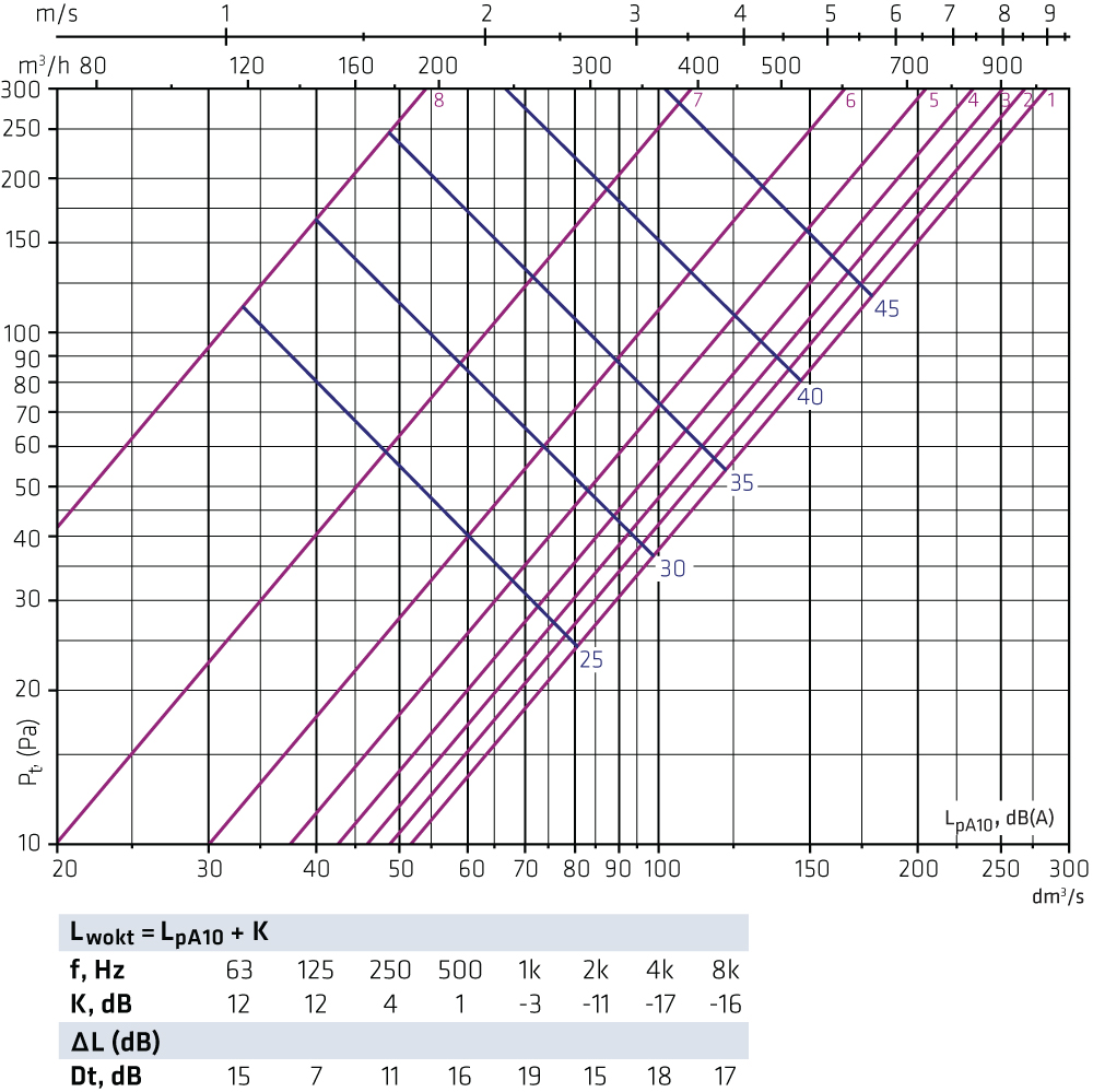
Selection diagrams FLO + OLEThe graphs are not intended for adjusting. FLO-100-125 + OLE-125 Supply air
FLO-100-160 + OLE-160 Supply air
FLO-125-125 + OLE-125 Supply air
FLO-125-160 + OLE-160 Supply air
FLO-125-200 + OLE-200 Supply air
FLO-160-160 + OLE-160 Supply air
FLO-160-200 + OLE-200 Supply air
FLO-160-250 + OLE-250 Supply air
FLO-200-200 + OLE-200 Supply air
FLO-200-250 + OLE-250 Supply air
FLO-200-315 + OLE-315 Supply air
FLO-250-250 + OLE-250 Supply air
FLO-250-315 + OLE-315 Supply air
FLO-315-315 + OLE-315 Supply air
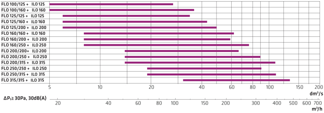
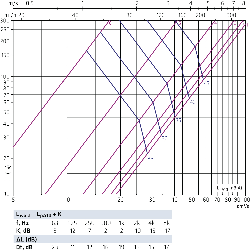
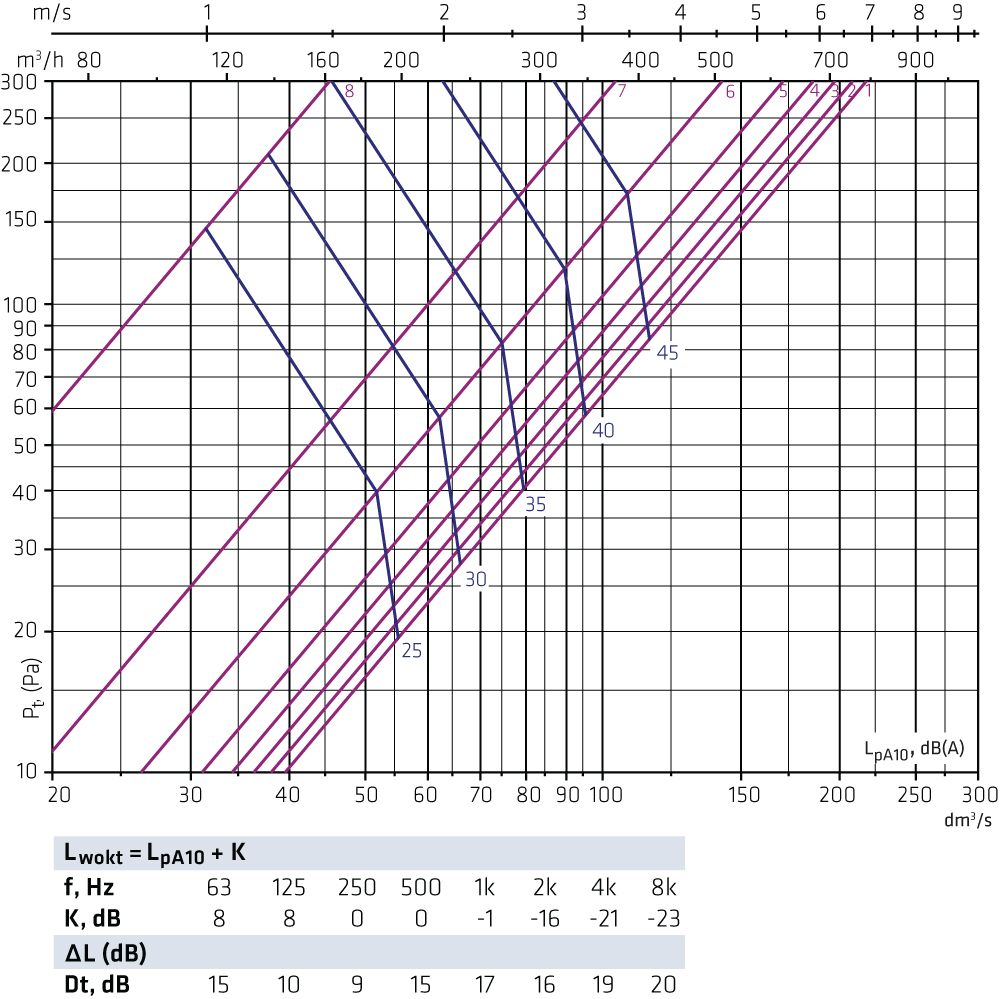
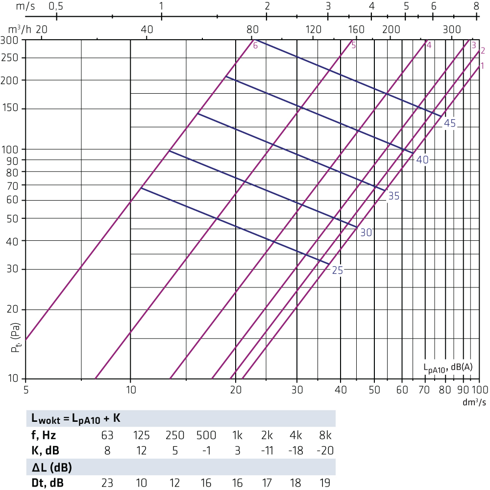
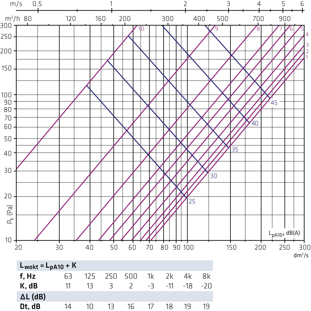
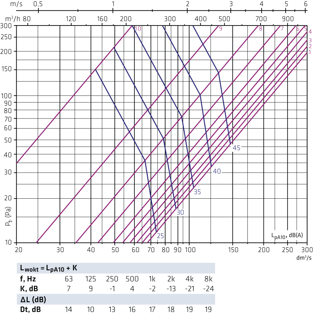
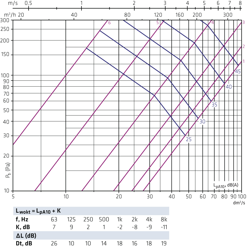
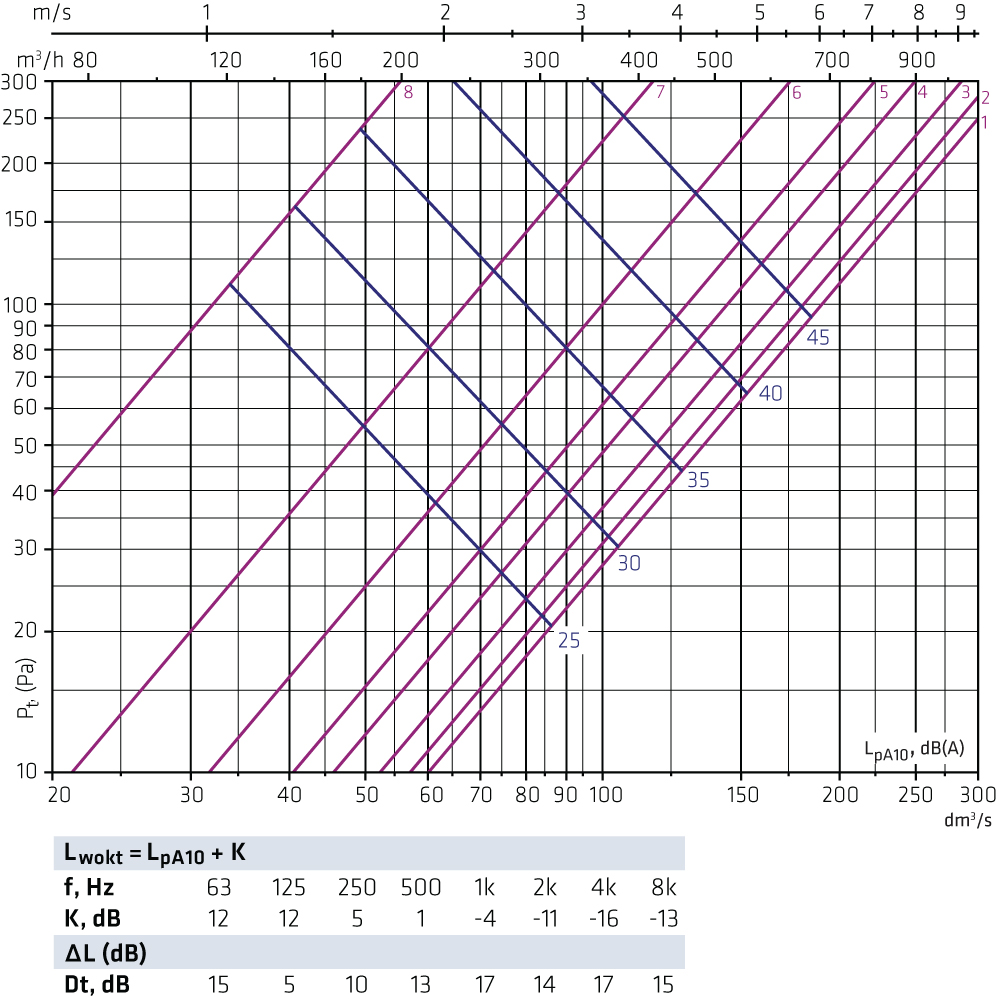
Selection diagrams FLO + ILOThe graphs are not intended for adjusting. FLO-100-125 + ILO-125
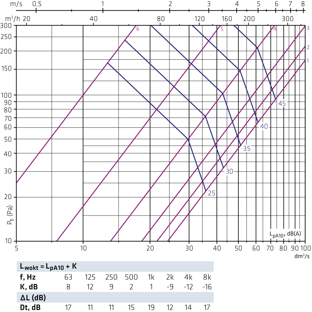
FLO-100-160 + ILO-160
FLO-125-125 + ILO-125
FLO-125-160 + ILO-160
FLO-125-200 + ILO-200
FLO-160-160 + ILO-160
FLO-160-200 + ILO-200
FLO-160-250 + ILO-250
FLO-200-200 + ILO-200
FLO-200-250 + ILO-250
FLO-200-315 + ILO-315
FLO-250-250 + ILO-250
FLO-250-315 + ILO-315
FLO-315-315 + ILO-315
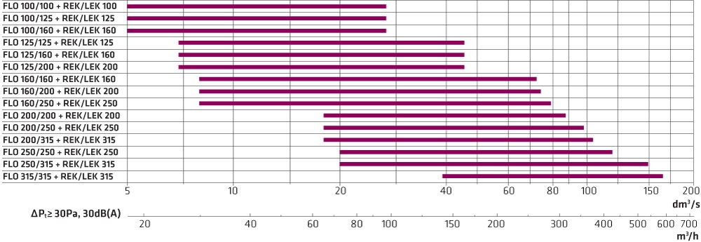
Selection diagrams FLO + REK/LEK supply airThe graphs are not intended for adjusting. FLO-100-100 + REK/LEK-100
FLO-100-125 + REK/LEK-125
FLO-100-160 + REK/LEK-160
FLO-125-125 + REK/LEK-125
FLO-125-160 + REK/LEK-160
FLO-125-200 + REK/LEK-200
FLO-160-160 + REK/LEK-160
FLO-160-200 + REK/LEK-200
FLO-160-250 + REK/LEK-250
FLO-200-200 + REK/LEK-200
FLO-200-250 + REK/LEK-250
FLO-200-315 + REK/LEK-315
FLO-250-250 + REK/LEK-250
FLO-250-315 + REK/LEK-315
FLO-315-315 + REK/LEK-315
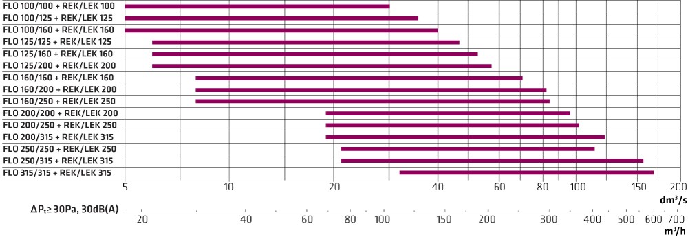
Selection diagrams FLO + REK/LEK exhaust airThe graphs are not intended for adjusting. FLO-100-100 + REK/LEK-100
FLO-100-125 + REK/LEK-125
FLO-100-160 + REK/LEK-160
FLO-125-125 + REK/LEK-125
FLO-125-160 + REK/LEK-160
FLO-125-200 + REK/LEK-200
FLO-160-160 + REK/LEK-160
FLO-160-200 + REK/LEK-200
FLO-160-250 + REK/LEK-250
FLO-200-200 + REK/LEK-200
FLO-200-250 + REK/LEK-250
FLO-200-315 + REK/LEK-315
FLO-250-250 + REK/LEK-250
FLO-250-315 + REK/LEK-315
FLO-315-315 + REK/LEK-315
FasteningFastening with a threaded rod takes place from inside the FLO plenum box. Therefore its length does not have to be determined very precisely. This also enables fasting to the ceiling surface. |